Lighting / Fixtures
Installation Guide for Golden Lighting 2072-FM41 Flush Mount
Step-by-step installation guide for the Golden Lighting 2072-FM41 flush mount fixture, including wiring instructions, mounting procedures, and safety guidelines.
Quick answers from the manual
Quick answer
- This document provides installation instructions for the Golden Lighting 2072-FM41 flush mount fixture, including wiring and mounting steps. p. 3, 4
Key actions
- Shut off power at the circuit breaker before starting. p. 3
- Connect Hot to Hot, Neutral to Neutral, and Ground to Ground. p. 3
First start
- Install light bulbs (not included) into sockets (I) according to specifications. p. 3
Where to find it in the PDF
- Lighting Tips p. 1
- Wiring Diagram p. 2
- Installation Instructions p. 3, 4
Table of contents
Manual images
Click an image to enlargeQuick Guide from the Manual
This document provides instructions for the safe installation of the Golden Lighting 2072-FM41 flush mount fixture. Before beginning, ensure the power is shut off at the circuit breaker. Installation should be performed by an accredited professional. The fixture arrives assembled and ready for installation.
Preparing for Installation
Carefully remove the fixture from the carton and locate the parts bag. Ensure the power is off at the circuit breaker and remove the old fixture and mounting strap from the wall.
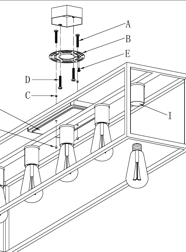
- Take the mounting strap assembly (B) from the parts bag.
- Attach the mounting screws (A & D) to the mounting strap (B).
- Test the canopy (F) against the mounting strap to determine how far to insert the screws.
- Tighten the nuts (C) to hold the screws in place.
- Secure the mounting strap (B) to the junction box using mounting screws (D).
Wiring Instructions
Refer to the wiring diagram on page 2 for proper connections. Have an assistant support the fixture's weight during this process.
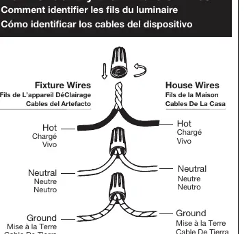
- Hot to Hot: Connect the fixture's hot wire (smooth, black, or transparent with black inner thread) to the house hot wire.
- Neutral to Neutral: Connect the fixture's neutral wire (ribbed, white, or transparent with white inner thread) to the house neutral wire.
- Ground to Ground: Connect the fixture's ground wire (copper, bare, green, or transparent with green inner thread) to the house ground wire.
- Twist the ends of the wire pairs together and secure with a wire connector. Ensure all twists are in the same direction.
- If there is no house ground wire, wrap the fixture's ground wire around the ground screw (E) on the mounting bracket.
Finishing the Installation
Once wiring is complete, tuck the wires into the junction box.
- Hold the canopy (F) over the mounting strap (B) so the holes align.
- Thread the decorative nuts (G) onto the exposed threads of the mounting screws (A) until the canopy is snug against the ceiling.
- Install the appropriate light bulbs (not included) into the sockets (I) according to the fixture's specifications. Do not exceed the maximum wattage.
- Turn on the power and test the fixture.
Manufacturer information
Golden Lighting
Practical help
Common problems
Fixture does not light up after installation
Verify that the power is turned on at the circuit breaker and ensure the light bulbs are properly installed and functional.
Unsure about wire identification
Consult the wiring diagram on page 2. Hot wires are smooth/black/transparent with black thread; Neutral wires are ribbed/white/transparent with white thread; Ground wires are copper/bare/green/transparent with green thread.
Before use
- Shut off power supply at the fuse or circuit breaker.
- Ensure you have an assistant to support the fixture's weight during wiring.
- Verify you have the correct light bulbs (do not exceed maximum wattage).
- Ensure the junction box is secure and suitable for the fixture.
Images and diagrams
- The wiring diagram illustrates the correct connection of Hot, Neutral, and Ground wires using wire connectors.
- The assembly diagram shows the mounting strap (B) attached to the junction box, with screws (A) and (D) securing the canopy (F) to the ceiling.
Model compatibility
- Ensure the junction box is capable of supporting the weight of the fixture.

Manual page author
Emily Carter
User documentation editor
Prepares concise manual descriptions and highlights the most useful setup, operation, and maintenance information for readers.