Lighting / Fixtures
Installation Manual for Golden Lighting 1768-FM Ciara Flush Mount
Step-by-step installation guide for the Golden Lighting 1768-FM Ciara 3-Light Flush Mount. Includes wiring diagrams, assembly instructions, and safety precautions for mounting.
Quick answers from the manual
Quick answer
- This manual provides instructions for installing the Golden Lighting 1768-FM flush mount fixture, including wiring connections and glass panel assembly. p. 3
Key actions
- Prepare for installation p. 3
- Connect wires p. 2, 3
- Finish installation p. 3
Where to find it in the PDF
- General lighting placement advice p. 1
- Wiring diagram and parts identification p. 2
- Assembly instructions p. 3
Table of contents
Manual images
Click an image to enlargeQuick Guide from the Manual
This document provides installation instructions for the Golden Lighting 1768-FM Ciara Flush Mount. All installation work must be performed by an accredited professional. Before starting, ensure the power supply is shut off at the fuse or circuit breaker. Do not exceed the maximum wattage specified for the bulbs.
Installation Steps
- Preparation: Carefully remove the fixture from the carton and locate the yellow bag containing all parts. Remove the old fixture and the old mounting strap from the wall.
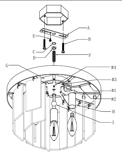
- Mounting: Ensure the mounting strap (A) has one end of the nipple (F) attached with the hex nut and washer (C & D). Attach the mounting strap (A) to the junction box using the provided mounting screws (B) and a screwdriver. Tighten securely.
- Wiring: Have an assistant support the fixture's weight. Connect the fixture wires to the power supply wires from the junction box according to the wiring diagram (Hot to Hot, Neutral to Neutral, Ground to Ground). Twist the ends of the wire pairs together and secure with a wire connector. Ensure all twists are in the same direction. If there is no house ground wire, wrap the fixture's ground wire around the ground screw (E) on the mounting bracket. Tuck the wires into the junction box.
- Finishing: Raise the ceiling pan (G) to cover the mounting strap (A). Secure it in place by threading the decorative nut (I) onto the exposed threads of the nipple (F).
Wiring Identification
Properly identify your wires before connecting:
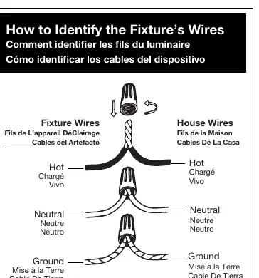
- Hot Wire: Smooth, black, or transparent with black inner thread.
- Neutral Wire: Ribbed, white, or transparent with white inner thread.
- Ground Wire: Copper, bare metal, green, or transparent with green inner thread.
Glass Panel Assembly
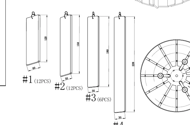
After the fixture is mounted, hang the glass panels as depicted in the assembly diagram. The fixture uses four types of glass panels (#1, #2, #3, and #4). Install the light bulbs (not provided) into the sockets (H) according to the fixture's specifications.
Lighting Placement Tips
For optimal lighting, consider the following guidelines:
- Kitchen Islands: Center a linear pendant over the island. Use one pendant for every 24 inches of island length. Fixtures should hang at least 30 inches above the countertop.
- Dining Tables: Fixtures should hang at least 30 inches above the table. Use a fixture that is 12 inches narrower than the width of the table.
- Open Areas: The bottom of the fixture should hang at least 7.5 feet from the floor. Ensure there is clearance for any opening doors.
Manufacturer information
Golden Lighting
Practical help
Common problems
Fixture weight during installation
Have an assistant support the weight of the fixture while you complete the wiring.
No house ground wire available
Locate the ground screw (E) on the mounting bracket and wrap the fixture's ground wire around it.
Identifying wires
Use the provided guide: Hot wires are smooth/black, Neutral wires are ribbed/white, and Ground wires are green/copper/bare metal.
Before use
- Shut off power supply at the circuit breaker.
- Remove the old fixture and old mounting strap.
- Verify all parts are present in the yellow bag.
- Ensure an assistant is available to support the fixture weight.
- Check that the junction box is secure.
Specs in practice
- Neutral Wire
- Ribbed, white, or transparent with white inner thread.
Images and diagrams
- Wiring Diagram: Illustrates how to connect house wires to fixture wires using connectors.
- Parts Diagram: Shows the assembly of the mounting strap (A), nipple (F), ceiling pan (G), and decorative nut (I).
- Glass Panel Diagram: Shows the specific sequence and placement for glass panels #1, #2, #3, and #4.
Model compatibility
- Use only specified bulbs.
- Do not exceed the maximum wattage.

Manual page author
Michael Turner
Technical manual editor
Reviews PDF manuals for structure, safety notes, and practical product details so readers can find the right information quickly.