Electronics / Video Transmission
User Manual for 18Gbps HDBaseT Extender with KVM Function
Comprehensive user guide for the 18Gbps HDBaseT Extender with KVM. Includes installation steps, connection diagrams, IR setup, EDID management, and technical specifications for 4K video extension.
Quick answers from the manual
Quick answer
- This device is an 18Gbps HDBaseT Extender that transmits HDMI, USB KVM, and IR signals up to 150m over a single CAT6 cable. It supports 4K@60Hz resolution and Power over Cable (POC). p. 3
Key actions
- Connect the transmitter and receiver using a CAT6 cable. p. 6, 7
- Set the EDID DIP switch on the transmitter. p. 6
First start
- Connect the power supply to either the transmitter or receiver. p. 6, 7
Problems and fixes
Link Signal Indicator (Green) is flashing
The connection between the transmitter and receiver is poor. Check the CAT6 cable.
p. 6, 7
Data Signal Indicator (Yellow) is dark
There is no HDMI signal. Check the source device and HDMI cable.
p. 6, 8Technical specifications
| Parameter | Value | Meaning | Pages |
|---|---|---|---|
| Resolution | 4K2K@60Hz YUV 4:4:4 | Maximum supported video resolution. | p. 4 |
| Transmission Distance | 150m (1080p), 120m (4K) | Maximum cable length for signal transmission. | p. 4 |
Where to find it in the PDF
- Transmitter Panel p. 6
- Receiver Panel p. 7
- Application Example p. 9
Table of contents
Manual images
Click an image to enlargeQuick guide from the manual
This 18Gbps HDBaseT Extender allows you to extend HDMI, bi-directional IR control, and USB KVM signals up to 150m using a single CAT6 cable. It supports resolutions up to 4K2K@60Hz YUV 4:4:4 and features Power over Cable (POC) functionality, meaning only one unit needs to be connected to the power supply.
Package Contents
- 1 x 18Gbps HDBaseT Extender (Transmitter)
- 1 x 18Gbps HDBaseT Extender (Receiver)
- 1 x IR Blaster cable (1.5 meters)
- 1 x IR Receiver cable (1.5 meters)
- 1 x USB cable (1.5 meters)
- 4 x Mounting Ears
- 8 x Machine Screws (KM3*4)
- 1 x 24V/1A Locking Power Supply
Transmitter Panel
The transmitter includes the following key controls and indicators:
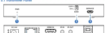
- EDID DIP Switch: Set to COPY (default) to copy EDID from the receiver's display, or STD for default 1080P 2CH.
- PWR LED: Indicates power status.
- Link Signal Indicator (Green): Illuminates when the connection between transmitter and receiver is good.
- Data Signal Indicator (Yellow): Illuminates when HDMI signal with HDCP is present.
- Ports: Includes HDMI IN, IR IN/OUT, HDBT OUT, and USB (PC connection).
Receiver Panel
The receiver includes the following key controls and indicators:
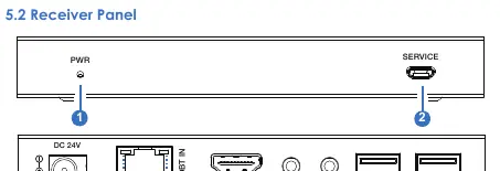
- Link Signal Indicator (Green): Shows connection status with the transmitter.
- Data Signal Indicator (Yellow): Shows HDMI signal status.
- Ports: Includes HDBT IN, HDMI OUT, IR IN/OUT, and 2 x USB-A ports for keyboard and mouse.
Installation and Application
To set up the system:
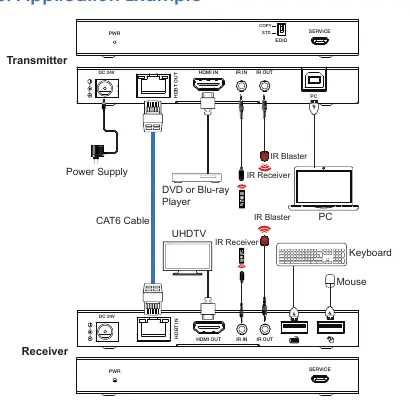
- Connect the HDMI source (e.g., DVD player) to the Transmitter's HDMI IN port.
- Connect the Transmitter's HDBT OUT to the Receiver's HDBT IN using a high-quality CAT6 cable.
- Connect the display (e.g., UHDTV) to the Receiver's HDMI OUT port.
- Connect the power supply to either the Transmitter or the Receiver (POC function).
- Connect USB devices (keyboard/mouse) to the Receiver and the PC to the Transmitter's USB port for KVM functionality.
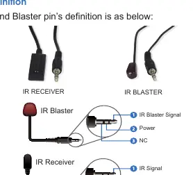
IR Pin Definition
The system supports bi-directional IR control. Ensure the IR Receiver and IR Blaster cables are connected correctly. The transmission distance for IR signals is 0-5 meters at a ±45° angle, and 0-8 meters at a ±90° angle.
Specifications
- HDMI Compliance: HDMI 2.0b, HDCP 2.2
- Video Resolution: Up to 4K2K@60Hz YUV 4:4:4
- Transmission Distance: 150m (1080P@60Hz), 120m (4K@60Hz)
- Power Supply: DC 24V/1A (POC supported)
- Operating Temperature: 0°C ~ 40°C
Practical help
Common problems
No signal on display
Check HDMI connections, ensure the Data Signal Indicator (Yellow) is illuminated, and verify the source device is active.
Poor connection between units
Check the CAT6 cable integrity. If the Link Signal Indicator (Green) is flashing, the connection is unstable.
IR control not working
Verify the IR Receiver and Blaster cables are plugged into the correct ports and that the remote control is within the specified angle and distance.
Before use
- Ensure you are using a high-quality CAT6 cable for the HDBaseT connection.
- Set the EDID DIP switch on the transmitter to the desired mode (COPY or STD).
- Connect the 24V/1A power supply to either the transmitter or the receiver (POC).
- Verify all HDMI and USB cables are securely connected.
Specs in practice
- POC (Power over Cable)
- Allows the system to be powered by a single power supply connected to either the transmitter or the receiver.
Images and diagrams
- The application example shows the transmitter connected to a PC and DVD player, and the receiver connected to a UHDTV, keyboard, and mouse.
- The IR pin definition diagram illustrates the wiring for the IR Receiver and IR Blaster cables.
Model compatibility
- Supports HDMI 2.0b and HDCP 2.2.
- Requires CAT6 cable for optimal performance.
- Supports USB 1.1 for KVM functionality.

Manual page author
Michael Turner
Technical manual editor
Reviews PDF manuals for structure, safety notes, and practical product details so readers can find the right information quickly.