Lighting / Outdoor Lighting
Installation and Assembly Guide for Hinkley 2563 Outdoor Lantern
Complete installation and assembly guide for the Hinkley 2563 outdoor lantern. Includes step-by-step instructions for post mounting, glass replacement, and electrical wiring.
Table of contents
Manual images
Click an image to enlargeQuick guide from the manual
This document provides assembly, installation, and maintenance instructions for the Hinkley 2563 outdoor lantern. Safety Warning: Always turn off the power supply before beginning any installation. If you are not comfortable with electrical wiring, consult a qualified electrician. For outdoor installations, ensure all wire connections are sealed with silicone sealant to prevent water ingress.
Assembly
To access the sockets for bulb installation:
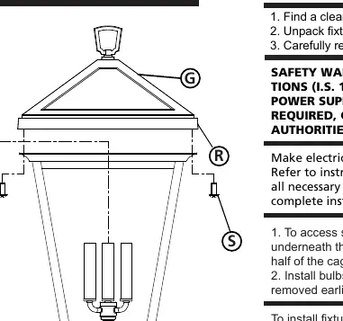
- Remove the two screws (S) from underneath the roof edge (R).
- The top half of the cage (G) can then be lifted off.
- Install the bulbs.
- Replace the cage bottom half and secure it using the screws (S) removed earlier.
Glass Replacement
The fixture allows for glass replacement on both the top and bottom sections.
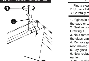
Top Glass Replacement
- Remove the bottom half of the cage or the top roof, depending on your specific fixture configuration.
- Remove the screw (1) holding the glass clip (2).
- Remove the glass panel (3) and the silicone gasket.
- Place the gasket on the new glass, slide the glass into the cage roof, ensuring the top edge is behind the tab (T).
- Center the glass, replace the clips (2), and secure with the screws (1).
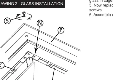
Bottom Glass Replacement
- Remove the top of the cage.
- Remove the four screws (S) in the corners of the bottom cage top casing (P) and lift the casting off.
- Bend the glass clips (C) up to remove the glass panel (G).
- Align the new glass panel with the notch (N) in the metal top band (M) and slide it into place.
- Bend the clips back to secure the glass, then reassemble the top casting.
Post Mounting
The fixture is designed to be mounted to an installed post.
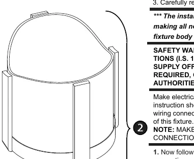
- Make all necessary electrical connections first (see Wiring section).
- Slide the post fitter (1) of the fixture body (2) over the installed post.
- Tighten the three machine screws (3) in the post fitter to secure the fixture.
Optional Mounting (Recommended for high wind/coastal areas):
- Slide the post fitter over the post and mark the location of the three threaded mounting holes.
- Remove the fixture, drill holes at the marked locations using a #29 drill bit (3.5mm).
- Tap the holes with an 8-32 UNC tap.
- Secure the fixture using the screws. If the post is thin-walled (1/16" or 2mm thick or less), replace machine screws with #8 stainless steel sheet metal screws.
Wiring and Grounding
Follow these steps for electrical connections:
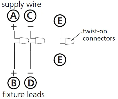
- Positive Wire (A): Typically black or the smooth side of the cord. Connect to the positive fixture lead (B) using a twist-on connector.
- Negative Wire (C): Typically white or the ribbed side of the cord. Connect to the negative fixture lead (D).
- Ground Wire (E): Typically copper or green. Connect to the power supply ground inside the post.
- Sealant: Cover the open end of connectors with silicone sealant to form a watertight seal.
Manufacturer information
Hinkley Lighting
Practical help
Common problems
Water entering the fixture
Ensure all wire connectors are covered with silicone sealant. If wall-mounted, use caulk to seal gaps between the mounting plate and the wall.
Fixture is loose on the post
Ensure the three machine screws (3) in the post fitter (1) are tightened securely. For high wind areas, consider drilling and tapping the post for a more secure fit.
Before use
- Turn off the main power supply
- Verify all parts are present
- Ensure silicone sealant is available for outdoor connections
- Check if the post is thin-walled (requires sheet metal screws)
- Have a #29 drill bit and 8-32 UNC tap ready if performing optional secure mounting
Specs in practice
- Silicone sealant
- Essential for creating a watertight seal on outdoor electrical connections.
- #29 drill bit
- Required size (3.5mm) for drilling holes in the post for secure mounting.
Images and diagrams
- Drawing 4 (Page 1): Shows the assembly and bulb access points.
- Drawing 1 & 2 (Page 2): Illustrates the glass replacement procedure for top and bottom sections.
- Drawing 1 (Page 3): Details the post mounting process and optional drilling/tapping steps.
- Drawing 1-3 (Page 4): Wiring and grounding diagrams for different fixture types.
Model compatibility
- Glass replacement instructions apply to models 2560, 2561, 2562, 2564, and 2565.

Manual page author
David Miller
Documentation analyst
Organizes user manual content into clear summaries, with attention to model details, product context, and everyday usability.