Lighting / Fixtures
Installation Manual for Hinkley 1553BZ Taper LED Step Light
Quick installation guide for the Hinkley 1553BZ Taper LED Step Light. Includes mounting instructions, wiring diagrams, and safety guidelines for low-voltage outdoor lighting.
Table of contents
Manual images
Click an image to enlargeQuick guide from the manual
This document provides installation instructions for the Hinkley 1553BZ Taper LED Step Light. The fixture is designed for low-voltage operation (9-15V AC) and is suitable for wet locations.
Mounting the fixture
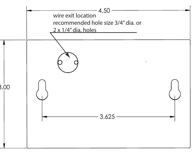
- Use the provided mounting template to mark the location on the mounting surface.
- Drill pilot holes at the indicated points using a 3/32 inch diameter drill bit.
- Install #6 Phillips head wood screws, leaving the base of the screw head 3/16 inch away from the mounting surface.
- If wiring passes through the mounting surface, drill the hole as indicated on the template.
Wiring instructions
The fixture requires an input voltage of 9-15 Volts AC. Connect the fixture wires to the supply wires using the provided wire nuts.
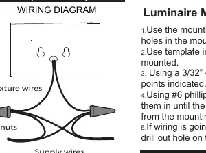
- Important: Apply the provided silicone glue to the inside of the wire nut before twisting it onto the wires to ensure a proper seal.
- Connect one fixture wire to the live supply wire and the other to the neutral supply wire.
Cable safety and installation
The main low-voltage cable from the transformer must adhere to the following safety guidelines:
- Route the cable in close proximity to the luminaire or building structure (e.g., house or deck).
- Do not bury the cable deeper than 6 inches (15.2 cm), except where necessary to connect to the main low-voltage cable.
- Ensure the cable is connected to a connector within 6 inches of a building structure, luminaire, or fitting.
Manufacturer information
Hinkley Lighting
Practical help
Common problems
Fixture not lighting
Verify the transformer output is between 9-15 Volts AC.
Moisture in wire connections
Ensure the provided silicone glue is applied inside the wire nuts before installation.
Before use
- Verify transformer output is 9-15V AC.
- Ensure you have #6 Phillips head wood screws.
- Check that the mounting surface is suitable for drilling.
- Confirm the mounting location allows for proper cable routing.
Specs in practice
- Input Voltage
- 9-15 Volts AC required for operation.
- Burial Depth
- Main cable should not be buried deeper than 6 inches.
Images and diagrams
- Wiring Diagram: Shows connection between fixture wires and supply wires using wire nuts.
- Mounting Template: Indicates 3.625 inch spacing between mounting holes and wire exit location.
Model compatibility
- For wet location use.

Manual page author
David Miller
Documentation analyst
Organizes user manual content into clear summaries, with attention to model details, product context, and everyday usability.