Lighting / Fixtures
Hinkley 51090 Integrated LED Bath Bar Installation Manual
Installation guide for Hinkley 51090, 51092, and 51093 integrated LED bath bars. Includes step-by-step instructions for glass installation, mounting plate attachment, and wiring safety precautions.
Quick answers from the manual
Quick answer
- This document provides installation instructions for Hinkley 51090, 51092, and 51093 LED bath bars, covering glass assembly and mounting plate installation. p. 1
Key actions
- Install glass p. 1
- Mount fixture p. 1
First start
- Turn off power, install glass, mount plate, connect wiring, and secure fixture. p. 1
Where to find it in the PDF
- Mounting Instructions p. 1
Table of contents
Quick guide from the manual
This document provides the necessary steps to install the Hinkley integrated LED bath bar. Before beginning, ensure you have a clear workspace and that the power supply is turned off at the circuit breaker. Note that the 8-32 screws required to secure the mounting plate to the junction box are not included with the fixture.
Glass installation
- Unscrew the knob (K) on the side of the fixture.
- Remove the screw (S) that holds the L arm (L) to the fixture.
- Remove the L arm (L) from the fixture.
- Remove the spacer (B) and glass cap (C) from the fixture.
- Slide the glass (G) onto the fixture.
- Replace the spacer (B) and glass cap (C).
- Replace the L arm (L), screw (S), and knob (K) to lock the glass into place.
Mounting the fixture
- Release the mounting plate (A) from the fixture by unscrewing the four barrel knobs (Z) on the front. Keep the screws (V) attached to the mounting plate.
- Secure the mounting plate (A) to the junction box using two 8-32 screws (not provided).
- Complete the wiring connections by referring to the IS-18 instruction sheet (provided separately).
- Replace the four barrel knobs (Z) to complete the fixture mounting.
- The fixture can now be powered on.
Safety and wiring
Warning: Always turn off the power supply during installation. If new wiring is required, consult a qualified electrician or local authorities for code requirements. Ensure you read the wiring and grounding instructions (I.S. 18) before completing any electrical connections.
Manufacturer information
Hinkley Lighting
Practical help
Common problems
Glass does not fit or is loose
Ensure the spacer (B) and glass cap (C) are correctly positioned before reattaching the L arm (L).
Mounting plate does not attach to junction box
Ensure you have purchased 8-32 screws, as they are not included with the fixture.
Before use
- Turn off power supply at the circuit breaker
- Clear a workspace for assembly
- Verify you have two 8-32 screws for the junction box
- Review the IS-18 wiring instruction sheet
Images and diagrams
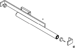
- Drawing 1 illustrates the sequence for glass installation, highlighting the L arm, spacer, and glass cap.
- Drawing 2 illustrates the mounting plate attachment to the junction box.
Model compatibility
- Requires IS-18 instruction sheet for specific wiring connections.

Manual page author
Emily Carter
User documentation editor
Prepares concise manual descriptions and highlights the most useful setup, operation, and maintenance information for readers.