Toys / RC Components
User Manual for Hobbywing QuicRun Fusion Pro Elite ESC/Motor System
Comprehensive user guide for the Hobbywing QuicRun Fusion Pro Elite 2-in-1 ESC/Motor system. Includes installation, wiring, ESC calibration, parameter settings, LED status indicators, and troubleshooting.
Quick answers from the manual
Quick answer
- The QuicRun Fusion Pro Elite is a 2-in-1 ESC/Motor system. Calibration is required on the first use or after changing the radio/receiver to ensure the ESC correctly identifies neutral, full throttle, and full reverse positions. p. 1
Key actions
- Calibrate the throttle range p. 1
- Perform automatic motor pairing p. 1
First start
- Set radio throttle settings (D/R, EPA, ATL to 100%, TRIM to 0), power off ESC, hold power button, and follow the 3-point calibration sequence. p. 1
Problems and fixes
Motor does not start
Check battery input, switch, and throttle signal.
p. 1
Car moves in reverse
Change Motor Rotation setting.
p. 1Maintenance and reset
- Use LED or LCD program box to restore factory settings via the RESET or Parameter Settings menu. p. 1
Technical specifications
| Parameter | Value | Meaning | Pages |
|---|---|---|---|
| Continuous/Peak Current | 50A/150A | Current handling capacity | p. 1 |
| BEC Output | 6V/7.4V/8.4V | Adjustable voltage for servos | p. 1 |
Where to find it in the PDF
- Main Manual p. 1
Table of contents
Quick Guide
The Hobbywing QuicRun Fusion Pro Elite is a 2-in-1 ESC/Motor system designed for 1/10 scale crawlers. Before first use, it is mandatory to calibrate the throttle range. Ensure all wires are properly insulated and the battery polarity is correct to avoid damage.
Installation and Connections
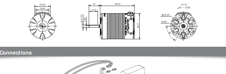
Motor Installation: The motor features 6xM3 screw holes with a 5mm depth. Ensure screw length is appropriate to avoid damaging the motor.
Wiring:
- Receiver: Connect the throttle cable to the throttle channel of the receiver. If the receiver requires power, ensure the red wire is handled correctly (do not supply power to the receiver if the ESC already provides BEC voltage).
- Yellow Signal Cable: Connects to the AUX/idle channel for real-time parameter adjustment via the transmitter.
- Battery: Connect the input line observing correct polarity (+ to +, - to -). Reverse polarity will damage the system.
ESC Calibration
Calibration is required on the first use or if a new radio/receiver is installed.
- Turn on the radio and set throttle channel D/R, EPA, and ATL to 100%, and TRIM to 0.
- With the ESC powered off, press and hold the power button. The red light will flash. Release the button.
- Neutral Position: With the throttle trigger at neutral, press the power button. The green light flashes once and the motor emits one beep.
- Full Throttle: Move the trigger to full throttle, press the power button. The green light flashes twice and the motor emits two beeps.
- Full Reverse: Move the trigger to full reverse, press the power button. The green light flashes three times and the motor emits three beeps.
Programmable Items
The system supports parameter settings via LED or LCD Program Box. Key settings include:
- Running Mode: Options include Forward/Reverse (RPM Matching) and Forward/Reverse with Brake.
- Cutoff Voltage: Prevents over-discharge of LiPo cells.
- Drag Brake Force: Adjustable for holding power on inclines.
- BEC Voltage: Adjustable (6V/7.4V/8.4V) to suit different servos.
Troubleshooting
If the system malfunctions, check the following:
- Motor does not start: Check battery connection, switch integrity, and throttle signal.
- Car moves in reverse: Adjust the "Motor Rotation" parameter via the program box.
- Throttle range calibration fails: Ensure the throttle cable is inserted correctly and the radio settings (D/R, EPA, TRIM) are correct.
- Overheat/Low Voltage: Check LED status codes. Green flashing indicates overheat; Red flashing indicates low voltage protection.
Manufacturer information
Hobbywing
Practical help
Common problems
Motor does not start / No indicator light
Check battery connection, ensure the plug is soldered correctly, and inspect the switch for damage.
Car moves in reverse when forward is commanded
Change the 'Motor Rotation' parameter to the opposite direction using the program box.
Throttle range calibration fails
Verify the throttle cable is in the correct receiver channel and not inserted reversely. Ensure radio settings (D/R, EPA, TRIM) are at default/neutral.
Before use
- Ensure all wires and connectors are well insulated.
- Remove the pinion gear before calibrating the system.
- Set throttle channel D/R, EPA, and ATL to 100% and TRIM to 0 on the transmitter.
- Verify battery polarity before connecting.
- Ensure the ESC switch is turned on with wheels off the ground.
Specs in practice
- Continuous/Peak Current
- 50A/150A rating for power handling.
Images and diagrams
- Wiring diagram shows the connection between the ESC, battery, receiver, and switch.
- Calibration steps illustrate the 3-point setup: Neutral, Full Throttle, and Full Reverse.
Model compatibility
- Designed for 1/10 scale crawlers.
- Supports 2-4S LiPo or 6-12 Cells NiMH batteries.
- Compatible with LED and LCD Program Box Pro/G2 for settings.

Manual page author
David Miller
Documentation analyst
Organizes user manual content into clear summaries, with attention to model details, product context, and everyday usability.