Toys / RC Models & Drones
User Manual for Holybro FETtec Mini AIO 15A
Quick guide for the Holybro FETtec Mini AIO 15A. Includes wiring diagrams, firmware update instructions via FETtec Configurator, OSD settings, and technical specifications.
Table of contents
Manual images
Click an image to enlargeQuick Guide
The FETtec Mini AIO 15A is a compact flight controller and ESC board. Important: Always remove propellers before flashing firmware or performing configuration to prevent accidents. Ensure your FC firmware is version 1.3RC45Y or later for compatibility.
Features
Flight Controller (FC):
- KISS FC firmware
- F3 Processor (STM32F303CCT6 @ 72MHz)
- Supply voltage: 6-18V (2S-4S Lipo)
- Dedicated onboard 5V BEC (max 1A)
ESC:
- Active current limiting @ 15A
- Input voltage: 2S-4S
- High quality 30V MOSFETs
- Automatic input signal detection (Dshot300-2400, PWM, OneShot42/125)
Wiring and Installation
The board features very small solder pads; use caution during soldering to avoid damage. The board has 3 UARTs:
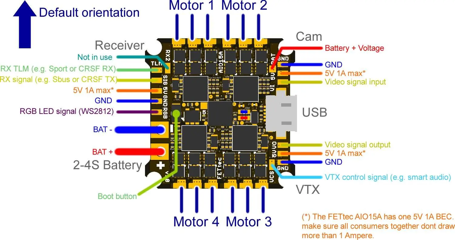
- UART 1: Onboard FETtec OSD or others (e.g., DJI Unit via bridge)
- UART 2: RX
- UART 3: VTX control (smart audio) + ESC telemetry
Refer to the connection diagram for specific pad locations for motors, receiver, camera, VTX, and battery input.
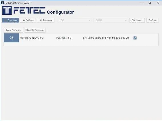
Firmware Updates
The FC, ESC, and OSD are flashable using the FETtec Configurator (available at https://github.com/FETtec). Connect via USB to update. For FC updates, select 'Remote Firmware' and flash the newest version. For ESC and OSD updates, use the 'KISS FC Passthrough' mode in the Configurator.
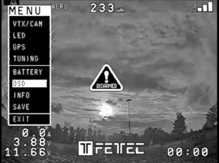
OSD Configuration
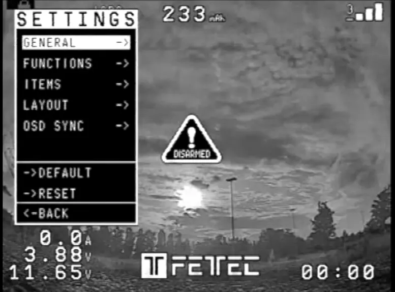
Settings are adjusted directly in the OSD. To enter the menu, set throttle to 50%, then move Yaw left and Pitch up. Use the OSD menu to adjust VTX/CAM, LED, GPS, Tuning, and Battery settings. If you experience blurry lines, adjust the LEFT/WITH values (avoid WITH values above 400) or perform a PAL/NTSC layout reset. Elements can be moved by selecting LAYOUT -> SET POSITIONS in the settings menu.
Official resources from the manual
Practical help
Common problems
Blurry lines in OSD
Adjust LEFT/WITH values in the OSD settings; try to avoid WITH values above 400.
OSD display issues
Set OSD SYNC to AUTO SYNC or perform a PAL/NTSC layout reset.
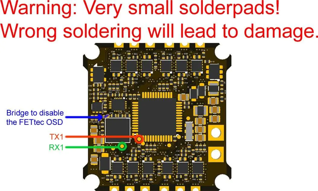
Risk of board damage
The solder pads are very small; ensure precise soldering to avoid bridging or damaging components.
Before use
- Remove propellers before flashing or configuration.
- Ensure firmware is version 1.3RC45Y or later.
- Check wiring against the connection diagram.
- Download and install the FETtec Configurator.
- Verify battery voltage is within 2S-4S range.
Specs in practice
- Active current limiting
- The ESC limits current to 15A to protect the hardware.
Images and diagrams
- Wiring Diagram: Shows connections for Receiver, Motors, Camera, VTX, and Battery.
- Solder Pads: Highlights the bridge to disable FETtec OSD and TX1/RX1 pads.
Model compatibility
- Works with KISS/FETtec FC firmware version 1.3RC45Y or later.
- Supports Dshot300-2400, PWM, OneShot42/125.

Manual page author
Emily Carter
User documentation editor
Prepares concise manual descriptions and highlights the most useful setup, operation, and maintenance information for readers.