HVAC / Parts & Accessories
Installation Instructions for Honeywell CTS-V and CTP-V Series Current Sensors
Installation and wiring guide for Honeywell CTS-V and CTP-V series current sensors. Learn how to mount, wire, and troubleshoot your 0-5/10Vdc output current monitoring device.
Table of contents
Manual images
Click an image to enlargeQuick guide from the manual
This document provides installation and wiring instructions for the Honeywell CTS-V and CTP-V series current sensors. These devices are designed for AC current monitoring applications and provide a 0-5Vdc or 0-10Vdc output signal. The sensors are intended for use on insulated conductors only and are not for life, safety, or hazardous location applications.
Installation
The sensor can be mounted in any position. Ensure all installations comply with national and local electrical codes.
- Mounting: Use the two #8 x 3/4 inch Tek screws through the base mounting holes, or snap the unit directly onto a 35mm DIN rail.
- Clearance: Maintain a minimum distance of 1 inch (2.6 cm) between the current sensor and other magnetic devices such as contactors, relays, or transformers.
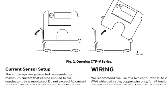
- Latch Operation (CTP-V Series): To open the split-core sensor, press down on the side tab and swing the top of the unit up. To close, press down firmly on the cover until an audible click is heard.
- Maintenance: Keep the mating surfaces of the magnetic core clean. Electrical contact grease is present to prevent corrosion; ensure no grit or dirt interferes with the contact between pole pieces.
Wiring
The sensor does not require external power, as it is induced from the monitored conductor.
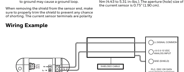
- Cable: Use a two-conductor 16 to 22 AWG shielded copper cable.
- Distance: The maximum wire length between the sensor and the controller should be less than 30 meters (98.4 feet).
- Grounding: Connect only one end of the shield to ground at the controller to avoid ground loops. Trim the shield at the sensor end to prevent shorting.
- Terminals: The terminals are polarity sensitive. Tighten terminal block screws to a torque of 0.5 to 0.6 Nm (4.43 to 5.31 in-lbs).
Troubleshooting
If you encounter issues, follow these steps:
- No reading: Verify current is flowing through the conductor using a clamp-on probe. Check circuit polarity and ensure terminals are securely tightened. Disconnect wires and measure voltage across the output with a voltmeter to verify sensor function.
- Erratic readings: Ensure wires are terminated properly. In areas with high RF interference, shielded cable is required to stabilize the signal.
- Inaccurate readings: If the sensor is not reading within specifications, contact the factory for assistance.
- Low-level/Failing operation: Visually inspect the mating parts of the core for debris. Clean manually and re-close the sensor.
Manufacturer information
Honeywell International Inc.
Practical help
Common problems
No reading
Verify current is flowing through the conductor, check circuit polarity, and ensure terminal screws are tight.
Erratic readings
Check wire terminations and ensure shielded cable is used to mitigate RF interference.
Inaccurate readings
Inspect the split-core mating surfaces for debris or dust and clean if necessary.
Before use
- Verify the application is not for life, safety, or hazardous locations.
- Ensure the conductor being monitored is insulated.
- Select the correct amperage range using the range selection jumper (factory set to high).
- Prepare 16-22 AWG shielded copper cable.
- Ensure 1 inch (2.6 cm) clearance from other magnetic devices.
Specs in practice
- Monitored Current Type
- AC Current only.
- Isolation Voltage
- 2200 VAC.
- Terminal Block Torque
- 0.5 to 0.6 Nm (4.43 to 5.31 in-lbs).
- Aperture Size
- 0.75 inches (1.90 cm).
Images and diagrams
- Fig 1: Shows mounting the sensor on a 35mm DIN rail.
- Fig 2: Illustrates the latch operation for opening and closing the CTP-V split-core sensor.
- Fig 3: Wiring diagram showing connection to an analog input on a controller.
Model compatibility
- Use only on insulated conductors.
- Not intended for life or safety applications.
- Not for use in hazardous or classified locations.

Manual page author
David Miller
Documentation analyst
Organizes user manual content into clear summaries, with attention to model details, product context, and everyday usability.