Lighting / Stage Lighting
User Manual for Ibiza FXBAR140 2-in-1 Blinder & Matrix Bar
Quick guide for the Ibiza FXBAR140 2-in-1 Warm White Blinder and RGB Matrix Animation Bar. Includes installation, DMX setup, menu navigation, and troubleshooting.
Quick answers from the manual
Quick answer
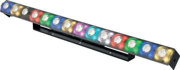
- The Ibiza FXBAR140 is a 2-in-1 warm white blinder and RGB matrix animation bar. It supports DMX-512 control, master/slave operation, and sound-controlled modes. p. 1, 4
Key actions
- Mounting the fixture p. 3
- Setting DMX Address p. 4
First start
- Connect to power, ensure proper voltage, and mount securely. p. 2, 3
Problems and fixes
No response to DMX
Check DMX LED, cables, address settings, and polarity.
p. 5Maintenance and reset
- Disconnect from mains before cleaning. Use a clean cloth to wipe dust. p. 4
Technical specifications
| Parameter | Value | Meaning | Pages |
|---|---|---|---|
| Power | 100W | Power consumption | p. 5 |
| Weight | 2.66kg | Unit weight | p. 5 |
Where to find it in the PDF
- Safety and Unpacking p. 2
- Installation and DMX p. 3
- System Menu p. 4
- Specifications and Troubleshooting p. 5
Table of contents
Manual images
Click an image to enlargeQuick guide from the manual
The Ibiza FXBAR140 is a 2-in-1 lighting fixture combining a warm white blinder and an RGB matrix animation bar. This manual provides essential instructions for safe installation, DMX configuration, and operation.
Safety and Unpacking
- Unpacking: Check the contents immediately upon receipt. Ensure all parts (FXBAR140, power cable, manual) are present and undamaged.
- Safety: This is a Class I appliance and must be connected to an earthed mains outlet.
- Environment: For indoor use only. Maintain at least 50cm distance from adjacent surfaces. Do not operate in temperatures exceeding 40°C.
- Maintenance: Disconnect from mains before cleaning or maintenance. Do not use aggressive cleaning agents.
Installation
The unit must be mounted securely via the screw holes on the bracket. Ensure the mounting structure can support at least 10 times the weight of the fixture. Never stand directly below the device during installation or servicing.
DMX Setup and Linking
To link multiple fixtures, use a serial data link with DMX-512 controllers or master/slave mode. Fixtures must be daisy-chained in a single line.
- Cabling: Use data-grade cables with a male XLR connector on one end and a female XLR connector on the other.
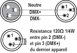
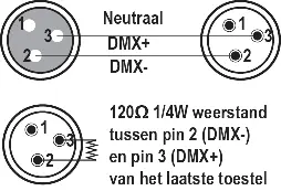
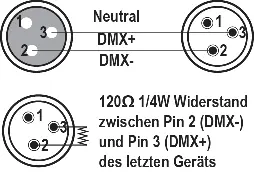
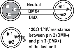
- Termination: To avoid signal errors, it is advisable to connect a DMX signal terminator (120 Ohm resistor between pin 2 and 3) to the last unit in the chain.
- Caution: Do not allow contact between the common and the fixture's chassis ground to prevent ground loops.
System Menu Operation
The LED display features 4 buttons: MENU, UP, DOWN, ENTER.
- ADDR: DMX Address Setting.
- CHND: DMX Channel Mode (6, 8, 12, or 60 channels).
- SLND: Master-Slave Mode (Mast, SL1, SL2).
- SoUn: Sound controlled mode (programs 0-59, sensitivity 00-99).
- AUTO: Auto running effect (programs 0-59, speed 1-9).
- COLO: Color selection (1-15).
- MANU: Manual color mixing (Red, Green, Blue, White 0-255).
- DISP: Display reverse by 180°.
- Ver: Displays device version.
Troubleshooting
If the unit does not work, check the power connection, main fuse, and mains voltage. If there is no response to the DMX controller, verify the DMX LED status, cable connections, address settings, and DMX polarity. If there is no response to sound, ensure the unit is not receiving a DMX signal and test the microphone.
Practical help
Common problems
Unit does not work, no light, no fan
Check the power connection, main fuse, and measure the mains voltage on the main connector.
No response to DMX controller
Check if the DMX LED is on. Verify DMX connectors, cables, address settings, and DMX polarity. Ensure cables are not running near high-voltage lines.
No response to sound
Ensure the unit is not receiving a DMX signal. Test the microphone by tapping it.
Before use
- Unpack and verify contents: FXBAR140, power cable, user manual.
- Ensure mains voltage matches the fixture rating.
- Verify the mounting structure can support 10x the unit's weight.
- Ensure adequate ventilation with at least 50cm clearance.
- Check that ventilation slots are not blocked.
Specs in practice
- Power supply
- 110-220V~ 50/60Hz
- Light source
- 14x 3W warm white CREE LEDs and 56x 3-in-1 5050 RGB LEDs
- DMX channels
- 6, 8, 12, or 60 channels
Images and diagrams
- XLR connector wiring: Pin 1 (Neutral), Pin 2 (DMX-), Pin 3 (DMX+).
- DMX termination: 120 Ohm resistor between pin 2 and 3 on the last unit.
Model compatibility
- Requires DMX-512 controller for advanced lighting shows.
- Supports master/slave operation for synchronized shows.
- Maximum recommended serial data link distance: 100 meters.
- Maximum recommended number of fixtures on a serial data link: 16.

Manual page author
David Miller
Documentation analyst
Organizes user manual content into clear summaries, with attention to model details, product context, and everyday usability.