Computers / Laptops
Installation Instructions for Cold Weather Kit for Gas Packaged Units
Installation guide for the Cold Weather Kit designed for LG/LD/KG/KD 092-300 and SG 120 gas packaged units. Includes wiring diagrams, component installation steps, and operational temperature thresholds.
Table of contents
Manual images
Click an image to enlargeQuick guide from the manual
This Cold Weather Kit is designed to heat the gas heat compartment of specific Lennox gas packaged units to ensure proper gas valve operation during low outdoor temperatures. Before beginning installation, ensure all power to the unit is disconnected and the heat access panel is open. Always wear gloves and protective clothing, as the unit contains sharp sheet metal edges. Verify your specific unit model against Table 1 in the manual to ensure you are using the correct kit and wire harnesses.
Application
The kit is compatible with LG/LD/KG/KD 092-300 and SG 120 gas packaged units. It functions by monitoring ambient temperature and energizing a heater assembly when temperatures drop below specific thresholds.
Installation
Installation procedures vary significantly based on the specific unit model. Follow the section corresponding to your unit:
- LGH092-150 Units: Install heater assembly, route harness 604954-01, and connect to K125 relay.
- KG, KD 092-150 Units: Route harness 604956-01, install heater assembly, and connect to K125 relay.
- LGM, LGT, LDT 092-150 Units: Install heater assembly, connect J/P228 power harness, and install K125 relay.
- LGH156-300 Units: Install heater assemblies and K125 relays, route harness 106051-01 (standard) or 105722-01 (high SCCR).
- KG, KD 156-300 Units: Install heater assemblies and K125 relays, route harness 604785-01.
- LGX, LDT, LGT, LGM 156-300 Units: Install heater assemblies and relays, route harness 107210-01.
- LGT/LDT 302-360 Units: Install heater assemblies and relays, route harness 108303-01.
- SG 120 Unit: Install heater and control assembly, connect harness 107824-01.
Operation
The kit operates based on ambient temperature sensors:
- Below 20°F (-7°C): S61 switch closes.
- Below -10°F (-23°C): S60 switch closes to energize K125 and activate the HR6 heater.
- At 20°F (-7°C): S60 opens to de-energize the heater.
- Below -20°F (-29°C): S59 opens to disable the GV1 gas valve.
- At 10°F (-12°C): S59 closes to allow heating.
Manufacturer information
LG Electronics
Practical help
Common problems
Unit not heating in cold weather
Verify that the S60 and S61 switches are functioning and that the K125 relay is properly energized.
Incorrect harness used
Ensure you are using the specific harness part number listed for your unit model in the installation instructions (e.g., 604954-01 vs 604956-01).
Before use
- Disconnect all power to the unit.
- Open the heat access panel.
- Verify kit part number against unit model using Table 1.
- Ensure you have the correct wire harnesses for your specific unit.
- Wear gloves and protective clothing to avoid injury from sharp edges.
Images and diagrams
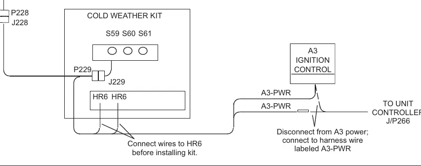
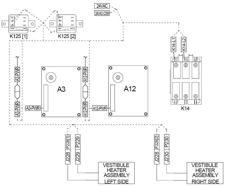
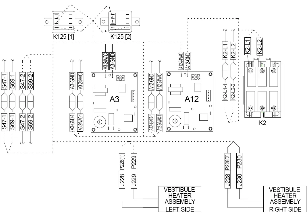
- Wiring diagrams illustrate the connections between the Cold Weather Kit, the Ignition Control (A3/A12), and the Unit Controller.
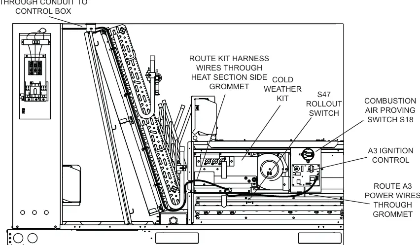
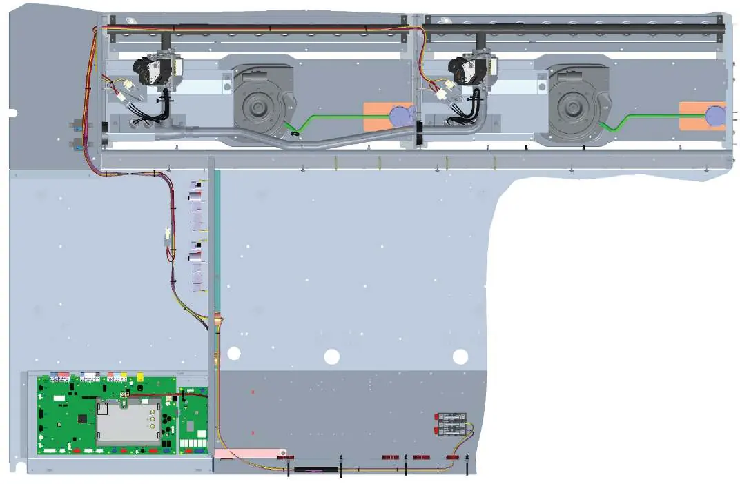
- Routing diagrams show the path for harness wires through grommets and conduits to the control box.
Model compatibility
- Compatible with LG/LD/KG/KD 092-300 and SG 120 gas packaged units.
- Specific harnesses are required for different unit models (e.g., Standard SCCR vs. High SCCR).

Manual page author
Michael Turner
Technical manual editor
Reviews PDF manuals for structure, safety notes, and practical product details so readers can find the right information quickly.