Plumbing / Sinks Faucets
Installation Manual for Matchmaster 04MM-RP01 Recessed Power Point Mounting Box
A comprehensive installation guide for the Matchmaster 04MM-RP01, RP02, and RP03 recessed power point mounting boxes. Includes step-by-step instructions for new and existing builds, safety warnings, and technical specifications.
Table of contents
Manual images
Jump to the sectionQuick guide from the manual
This document provides installation procedures for the Matchmaster 04MM-RP01, RP02, and RP03 recessed power point mounting boxes. Important: Installation must be performed by a suitably qualified installer or licensed electrician. Always turn off the power at the circuit breaker or fuse before beginning any work.
Safety Instructions
- Never install components during an electrical storm.
- Do not install in wet locations unless the components are specifically designed for such use.
- Do not use this product near water, such as bathtubs, sinks, or swimming pools.
- Never touch uninsulated wires or terminals unless the wiring has been disconnected at the network interface.
- Ensure no objects are pushed into the product openings to avoid contact with dangerous voltages.
Installation in New Builds
- Turn off the power at the circuit breaker or fuse and verify it is off.
- Select a wall location free from obstructions like timber frames or metal wall straps. Ensure there is no back-to-back wall point, as this affects wall depth.
- Cut a hole in the wall sheeting using the provided template. Check for obstructions in the wall cavity.
- For RP02 & RP03: Install the insert type to the bezel and direct connection cables through the brush opening before fitting to the wall cavity.
- Slide the power point through the back of the mounting box at an angle and push the housing into the cutout until it sits tight against the wall sheeting.
- If the wall sheeting is hard, mark the locations of the 2 top and 2 bottom fins and make small cuts to ensure the plastic shroud sits firmly.
- Insert the mounting box into the wall and secure it using the preinstalled floating clips in each corner.
- Position the power point into the housing and secure it using the 2 x 13mm screws provided into the metal brackets.
- Connect the cover. The unit is now ready for painting if required.
Installation in Existing Builds
- Turn off the power at the circuit breaker or fuse and verify it is off.
- Unscrew the existing point from the wall and check for obstructions.
- Push the existing wall point into the wall cavity through the existing stud bracket at an angle.
- Locate the back of the mounting box over the existing wall cutout so the existing bracket screw holes are visible through the rear of the mounting box.
- Mark the top and underside of the housing from the center of the mounting box to the side of the stud or trimmer.
- Cut approximately 2mm above the top line and 2mm below the bottom line towards the stud.
- Place the provided template over the wall sheeting from the located stud and mark around it.
- Continue cutting around the lines, ensuring you cut around the existing bracket.
- Cut vertically down the side where the stud or trimmer is located and remove the wall sheeting.
- Pry the existing bracket off the stud or trimmer and discard it.
- Proceed with the installation steps used for new builds (starting from step 4).
Technical Specifications and Compatibility
The mounting boxes are designed for 70mm and 90mm wall cavities. When installing multiple recessed points, ensure they are located more than 50mm apart vertically and/or horizontally. Note that the screw length used must not exceed 25mm.
Manufacturer information
Matchmaster Communications Pty Ltd
Practical help
Common problems
Wall depth or obstruction issues
Ensure the chosen location is free from timber frames or metal wall straps. Check for back-to-back wall points which may reduce available wall depth.
Hard wall sheeting preventing flush fit
Mark the locations of the 2 top and 2 bottom fins on the wall and make small cuts until the plastic shroud sits firmly against the sheeting.
Existing wall plate too large or cabling too tight
Disconnect the cabling from the back of the existing wall plate and reconnect it through the new recessed mounting box.
Before use
- Turn off power at the circuit breaker or fuse.
- Verify wall cavity depth is 70mm or 90mm.
- Check for obstructions in the wall cavity.
- Ensure no back-to-back wall points exist.
- Verify screw length does not exceed 25mm.
Specs in practice
- Wall Cavity Compatibility
- Designed specifically for 70mm and 90mm wall cavities.
- Screw Length Limit
- Screws must not exceed 25mm to prevent damage or protrusion.
- Minimum Spacing
- Maintain at least 50mm distance between multiple recessed points.
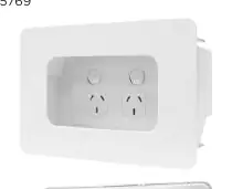
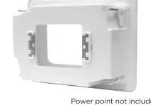
Images and diagrams
- The product images show the front bezel and the rear housing of the recessed mounting box.
Model compatibility
- Suitable for 70mm and 90mm wall cavities.
- Requires installation by a licensed electrician or technician.

Manual page author
Michael Turner
Technical manual editor
Reviews PDF manuals for structure, safety notes, and practical product details so readers can find the right information quickly.