Tools / Measuring Tools
User Manual for Metrel MicroOhm 10A (MI 3250) Low Resistance Ohmmeter
Quick guide for the Metrel MicroOhm 10A (MI 3250) low resistance ohmmeter. Learn about measurement modes, safety precautions, battery maintenance, and technical specifications.
Table of contents
Manual images
Click an image to enlargeQuick Guide from the Manual
The Metrel MicroOhm 10A (MI 3250) is a portable, bidirectional low resistance ohmmeter designed for measuring switches, relays, connectors, bus bars, and motor windings. It utilizes the four-wire Kelvin method to ensure high accuracy by eliminating test lead resistance.
Safety and Operational Considerations
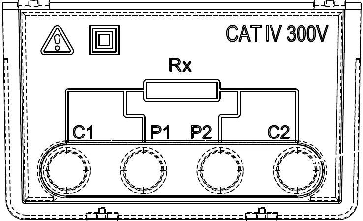
Important: Always ensure the object under test is de-energized before measurement. Do not touch the test object during measurement or before it is fully discharged. The instrument is rated CAT IV / 300 V. If the instrument is used in a manner not specified in this manual, the protection provided may be impaired.
Instrument Overview
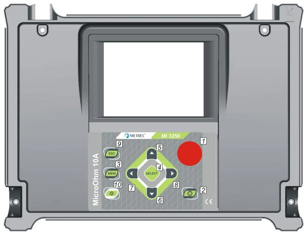
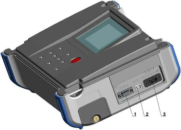
The front panel features a 320x240 dot matrix LCD and a keypad for navigation. Key buttons include START/STOP for measurements, MEM for memory management, and LIGHT for display backlight control. The connector panel includes four banana safety sockets for test leads (C1, C2, P1, P2), a mains socket for charging, and communication ports (USB and RS232).

Measurement Modes
The instrument offers five distinct measuring modes:
- Single Mode: Performs a single bidirectional measurement with thermal EMF elimination.
- Continuous Mode: Performs continuous bidirectional measurements, useful for troubleshooting.
- Automatic Mode: Starts a measurement automatically every time the test leads are connected to the object.
- Inductive Mode: Intended for inductive objects (motors, transformers); includes charging and discharging ramps.
- Unidirectional Mode: Similar to inductive mode but without charging/discharging ramps; allows setting measurement duration.
Settings and Memory
The Main Menu allows access to memory management, instrument settings, and help screens. You can save, recall, and delete test results. Settings include language selection, communication port configuration (USB/RS232), date/time, display contrast, and temperature compensation parameters.
Maintenance
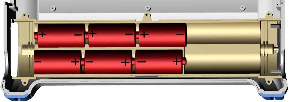
The instrument requires no special maintenance for the housing; clean with a soft cloth moistened with soapy water or alcohol. Ensure the instrument is dry before use. Periodic annual calibration is recommended. The battery compartment is accessible for replacing the six Ni-MH or Ni-Cd cells. Always disconnect all leads and switch off the instrument before opening the battery cover.
Technical Specifications
The device supports a wide measuring range from 0.1 µΩ to 2 kΩ with adjustable test currents from 1 mA to 10 A. It features internal memory for 1000 storage locations and supports PC connectivity via HVLink PRO software.
Practical help
Common problems
Battery low or weak
Replace or recharge cells. Do not use alkaline cells while the power supply adapter is connected.
Measurement error
Ensure the device under test has clean, oxide-free contacts. High resistance in the C1-C2 loop will cause errors.
Instrument unresponsive
Hold the LIGHT key for 5 seconds to perform a system reset.
High voltage warning
The instrument detects voltages higher than 8 V (AC or DC) between test terminals and will not perform the test.
Before use
- Check battery charge level.
- Ensure test leads are connected correctly (C1, C2, P1, P2).
- Verify the object under test is de-energized.
- Select the appropriate measurement mode for the object type.
- Ensure the instrument is in good condition and undamaged.
Specs in practice
- Four-wire Kelvin method
- Eliminates test lead resistance from the measurement for high accuracy.
- Thermal EMF elimination
- Automatic correction by measuring resistance in both directions (I+ and I-).
- CAT IV / 300 V
- Safety rating indicating the instrument is suitable for measurements in low-voltage installations.
Images and diagrams
- Front Panel: Shows the layout of the LCD and keypad buttons (1-10).
- Test Leads Connector: Details the C1/C2 current terminals and P1/P2 voltage terminals.
- Communication Panel: Shows the location of RS232, USB, and mains power ports.
Model compatibility
- Compatible with HVLink PRO PC software for data transfer.
- Supports USB and RS232 communication interfaces.
- Requires USB drivers to be installed on the PC for USB communication.

Manual page author
Emily Carter
User documentation editor
Prepares concise manual descriptions and highlights the most useful setup, operation, and maintenance information for readers.