Tools / Measuring Tools
Review and Specifications of Rigol DS1052E and Tektronix TBS1042 Oscilloscopes
A detailed technical review and comparison of the Rigol DS1052E and Tektronix TBS1042 digital storage oscilloscopes, featuring performance test results, usage tips, and comprehensive specifications.
Table of contents
Manual images
Click an image to enlargeQuick Guide from the Manual
This document provides a technical review and comparison of the Rigol DS1052E and Tektronix TBS1042 digital storage oscilloscopes. It serves as a reference for performance capabilities, key specifications, and operational tips for both units.
Technical Specifications
Both oscilloscopes are digital storage oscilloscopes (DSOs) suitable for amateur radio and general electronics testing. Key differences include bandwidth and interface options.
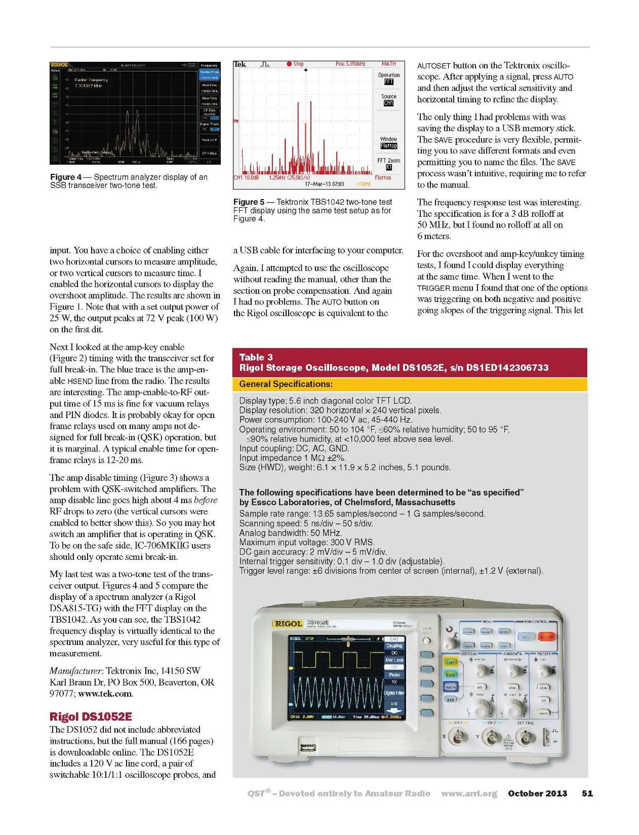
Rigol DS1052E Specifications
- Bandwidth: 50 MHz
- Channels: 2
- Sample Rate: 1 GSa/s (1 ch), 500 MSa/s (2 ch)
- Vertical Resolution: 8 bits
- Max Input Voltage: 300 V RMS
- Interface: USB (front and rear), RS232
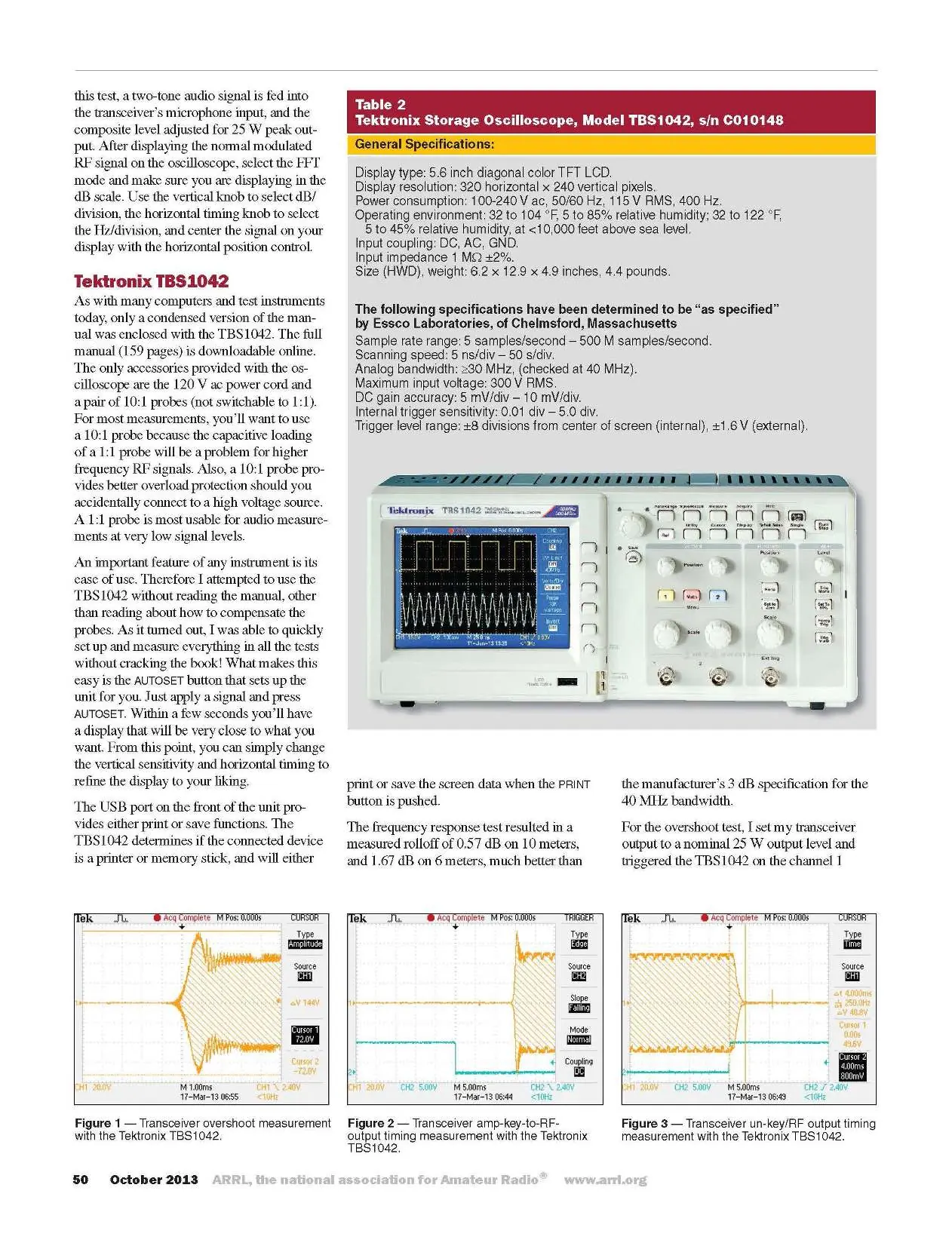
Tektronix TBS1042 Specifications
- Bandwidth: 40 MHz
- Channels: 2
- Sample Rate: 500 MSa/s
- Vertical Resolution: 8 bits
- Max Input Voltage: 300 V RMS
- Interface: USB (front and rear)
Usage and Operation
Both oscilloscopes feature an AUTOSET or AUTO button, which automatically configures the unit for the detected signal. This is the recommended starting point for new users.
Probe Compensation
Always ensure probes are compensated before making measurements. The manual provides specific sections on how to perform this adjustment to ensure accuracy.
Saving Data
Both units support saving screen data to a USB memory stick. Note that the save procedure on the Tektronix TBS1042 may require referring to the manual as the menu structure is not always intuitive.
Performance Testing
The review highlights several critical tests for amateur radio applications:
- Transceiver Overshoot: Measuring the initial power spike of a transceiver.
- Amp-Key Timing: Verifying the timing between the amplifier enable signal and RF output to prevent hot switching.
- Two-Tone Testing: Using the FFT (Fast Fourier Transform) math feature to display signals in the frequency domain, useful for checking transceiver linearity.
Practical help
Common problems
Hot switching in amplifiers
Amp disable timing may cause hot switching in QSK-switched amplifiers. Consider using semi break-in mode.
Transceiver overshoot
Transceiver output may overshoot on the first character; ensure ALC control is properly managed.
Before use
- Compensate probes before taking measurements.
- Verify power requirements (100-240V AC).
- Check bandwidth requirements for your specific application.
- Ensure proper probe selection (1:1 for low signal levels, 10:1 for high voltage/RF).
- Use the AUTOSET/AUTO button for initial signal configuration.
Specs in practice
- Vertical Sensitivity
- The range of voltage per division on the display (e.g., 2 mV/div).
Images and diagrams
- Figures 1-3: Transceiver overshoot and timing measurements.
- Figures 4-5: Spectrum analyzer vs FFT display comparison.
Model compatibility
- Rigol DS1052E: 50 MHz bandwidth.
- Tektronix TBS1042: 40 MHz bandwidth.

Manual page author
Emily Carter
User documentation editor
Prepares concise manual descriptions and highlights the most useful setup, operation, and maintenance information for readers.