Computers / Storage
User Manual for OWC Gemini 1GbE Storage and Dock
Comprehensive user guide for the OWC Gemini 1GbE storage enclosure and dock. Includes instructions for drive installation, RAID configuration, device setup, troubleshooting, and performance optimization.
Quick answers from the manual
Quick answer
- The OWC Gemini 1GbE is a dual-drive RAID storage enclosure and dock. It supports RAID 0, 1, Span, and Independent modes, and connects via Thunderbolt 3. p. 1, 8
Key actions
- Installing drives p. 6, 7
- Configuring RAID p. 8
First start
- Connect power and Thunderbolt cable to the system. p. 4, 5
Problems and fixes
Drive LED solid red
Drive failed, missing, or not connected properly.
p. 9, 13Maintenance and reset
- Replace failed drives with identical models. p. 9
Technical specifications
| Parameter | Value | Meaning | Pages |
|---|---|---|---|
| RAID Modes | 0, 1, Span, Independent | Configurable storage modes. | p. 8, 9 |
| Ports | Thunderbolt 3, USB 3.1 Gen 1, Ethernet, DisplayPort | Connectivity options. | p. 3, 4 |
Where to find it in the PDF
- System Requirements p. 2
- Assembly Steps p. 5, 6, 7
Table of contents
Manual images
Click an image to enlargeQuick guide from the manual
The OWC Gemini 1GbE is a dual-drive storage enclosure and dock. Before using the device, ensure your system meets the requirements: macOS 10.14 or later, or Windows 10 or later. The device supports 3.5"/2.5" SATA HDDs/SSDs and SD 4.0 cards. Always eject or unmount the device from your operating system before disconnecting it to prevent data loss.
Device Overview
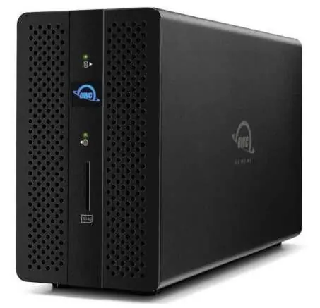
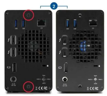
The front of the device features status LEDs for Drive A and Drive B, a Power LED, and an SD Media Slot. The rear panel includes USB 3.1 Gen 1 ports, an Ethernet port, a Kensington Security slot, a RAID selector dial, a DC IN power port, a DisplayPort, and two Thunderbolt 3 ports.
Assembly Steps
If you purchased the OWC Gemini as a bare enclosure, follow these steps to install drives:
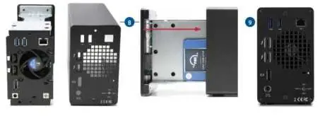
- Place the device on a static-free surface.
- Remove the two screws from the back of the enclosure and store them.
- Pull the front edge of the enclosure to slide out the inner chassis.
- Set the inner chassis flat on your work surface.
- Place a 2.5-inch or 3.5-inch SATA drive into the housing with the label facing upwards.
- Affix the drive to the inner chassis using the appropriate screws (one screw for 2.5" drives, eight screws for 3.5" drives).
- Slide the inner chassis back into the outer enclosure and secure it with the screws removed in step 1.
Hardware RAID Settings
The OWC Gemini supports multiple RAID modes, which must be selected before powering on the device:
- RAID 0 (Drive Striping): Combines capacities for speed. No data redundancy.
- RAID 1 (Drive Mirroring): Copies data to both drives for redundancy.
- Span: Combines capacities sequentially. No performance or redundancy benefits.
- Independent Drive Mode: Drives appear as separate disks.
To change the mode, use a paper-clip or flat-head screwdriver to rotate the RAID dial on the rear panel until the arrow aligns with the desired mode. The setting takes effect after powering on the device.
Device Management
If a drive fails, the corresponding front LED will light up solid red. For RAID 1, you can replace the failed drive to rebuild the array. For RAID 0, Span, or Independent modes, data on the failed drive is typically lost. Always replace failed drives with identical models (capacity, firmware) to ensure compatibility.
Troubleshooting
If you experience issues:
- Verify the power cable is connected and the power strip is on.
- Ensure the data cable is properly connected to both the computer and the Gemini.
- Try a different Thunderbolt 3 cable.
- If the rebuild LED is pulsing, wait for the process to complete (up to 48 hours).
- For slow read/write speeds on Windows, check the Disk Removal Policy and change it from 'Quick removal' to 'Better performance'.
Practical help
Common problems
Drive LED is solid red
The drive has failed, is missing, or is not connected properly.
Slow read/write speeds on Windows
Change the Windows Disk Removal Policy from 'Quick removal' to 'Better performance'.
Rebuild LED is pulsing
The RAID array is rebuilding. Wait for the process to complete (up to 48 hours).
Before use
- Verify power cable is connected to a power source.
- Ensure Thunderbolt cable is connected to a compatible system.
- Select the desired RAID mode using the rear dial before powering on.
- Ensure drives are identical (for RAID 0/1 configurations).
Images and diagrams
- Front LEDs indicate drive status (green/red) and power status (white/blue).
- Rear panel contains ports for USB, Ethernet, DisplayPort, and Thunderbolt 3.
- RAID selector dial is located on the rear panel.
Model compatibility
- Requires Thunderbolt 3 for full performance.
- Requires 1GbE Ethernet compatible hardware.
- Mac: macOS 10.14 or later.
- PC: Windows 10 or later.

Manual page author
Emily Carter
User documentation editor
Prepares concise manual descriptions and highlights the most useful setup, operation, and maintenance information for readers.