Electronics / Sim Racing Equipment
Instruction Manual for Sim-Lab Pedal Slider Baseplate
Quick guide for assembling the Sim-Lab Pedal Slider Baseplate. Includes installation steps, compatibility notes for various pedal sets, and a list of required tools.
Table of contents
Quick guide from the manual
The Sim-Lab Pedal Slider Baseplate is a modular component designed for sim racing cockpits. Before starting, verify that all parts are present by checking the bill of materials on page 14. Note that some extra parts may be included as spares. If you forget to install a Slot-Nut, you can insert it directly into the profile slot from the side without disassembling the entire structure.
Tools required
To assemble this product, you will need the following tools:
- Hex keys: 4mm, 5mm, 6mm
- Wrenches: 8mm, 10mm, 13mm
Assembly: Base Plate
- Identify the required Slot-Nuts (M8) and position them in the aluminum profile slots.
- Place the Pedal Base Plate (A1) onto the profile.
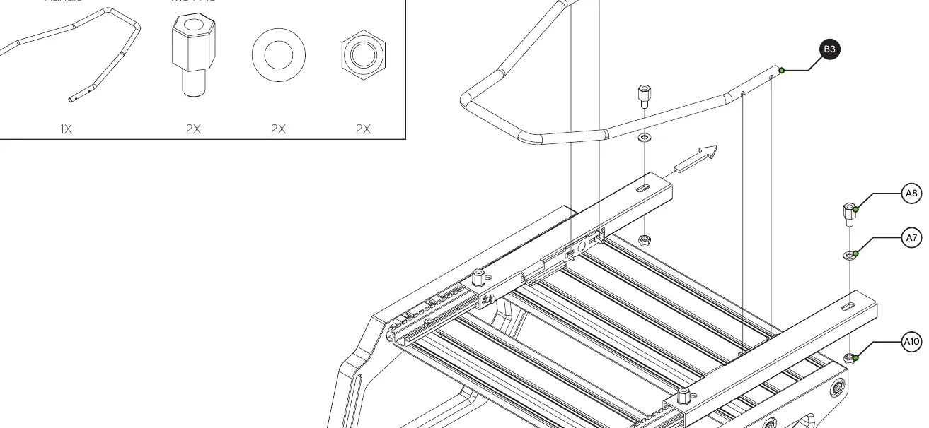
- Secure the plate using the provided M8 x 20 bolts (A6), spacers (A8), and washers (A7).
- Ensure all bolts are tightened securely.
Assembly: Pedal Sliders
If you are installing the optional pedal sliders:
- Attach the Left and Right Pedal Sliders (B1, B2) to the profile using M8 x 12 bolts (A3).
- Ensure the sliders move freely.
- Install the Pedal Slider Handle (B3). If the handle does not fit snugly, it may need to be slightly bent to fit between the sliders.
Assembly: Heel Rest
If you are installing the optional heel rest:
- Position the Heel Rest (C1) on the base plate.
- Secure it using the provided M6 x 45 bolts (C2), plastic sleeves (C4/C5), and lock-nuts (C6/C7).
Compatibility and Mounting
The baseplate is compatible with a wide range of pedal sets. Pages 15-17 of the manual provide specific hole patterns for various manufacturers, including:
- Asetek Invicta (2 and 3 pedal sets)
- Fanatec (Clubsport V3, CSL, T-LCM)
- Heusinkveld (Pro/Sprint/Ultimate)
- InSim Talento
- Logitech (Gxxx series and Pro)
- Meca Cup1
- SimCoach P1-3
- Simtrecs ProPedal GT
- Sim-Lab XP1
- Thrustmaster (T3PA, 2 Pedal Set)
- VRS Directforce Pro
Support
If you have questions regarding assembly, contact the support department at [email protected]. You can also join the Sim-Lab Discord server at www.sim-lab.eu/discord for community assistance.
Official resources from the manual
Practical help
Common problems
Pedal Slider Handle does not fit snugly
The handle may need to be widened slightly by bending it until it fits properly between the sliders.
Forgot to install a Slot-Nut
You can insert a Slot-Nut directly into the slot from the side. You can use a small hex wrench to help wiggle it into place.
Extra parts left over
This is intentional. The manufacturer supplies more parts than required for some entries as spares.
Before use
- Check the bill of materials on page 14 to ensure all parts are delivered.
- Gather required tools: 4/5/6mm hex keys and 8/10/13mm wrenches.
- Identify your specific pedal set to determine the correct mounting holes (see pages 15-17).
- Decide if you are installing optional pedal sliders or a heel rest before beginning assembly.
Specs in practice
- Spacer M8 x 15
- Component used to create necessary clearance during assembly.
Images and diagrams
- Pages 15-17 illustrate the specific mounting hole patterns for various pedal brands.
- Page 2 shows the correct method for inserting a Slot-Nut into the profile slot from the side.
Model compatibility
- Compatible with various cockpits; manual shows P1X PRO and GT1 EVO examples.
- Specific mounting patterns provided for Asetek, Fanatec, Simagic, Heusinkveld, InSim, Logitech, Meca, SimCoach, Simtrecs, Thrustmaster, and VRS.

Manual page author
Michael Turner
Technical manual editor
Reviews PDF manuals for structure, safety notes, and practical product details so readers can find the right information quickly.