HVAC / Thermostats & Controls
User Manual for White-Rodgers 1F80-224 Programmable Electronic Digital Thermostat
Quick guide for the White-Rodgers 1F80-224 thermostat. Learn how to install, program heating and cooling schedules, adjust settings, and troubleshoot common issues.
Quick answers from the manual
Quick answer
- The 1F80-224 is a programmable digital thermostat. Installation involves removing the old unit, labeling wires, mounting the base, and connecting wires according to the specific system diagram. Programming is done via the PRGM button. p. 1, 2, 6
Key actions
- Install batteries p. 2
- Enter configuration menu p. 4, 5
First start
- Remove battery tag, mount base, connect wires, and set current time/program. p. 2, 6
Problems and fixes
No Heat/Cool
Check fuse, furnace power switch, and wiring connections.
p. 7Maintenance and reset
- Reset thermostat by pressing the arrow buttons and TIME at the same time. p. 6
Technical specifications
| Parameter | Value | Meaning | Pages |
|---|---|---|---|
| Electrical Rating | 8 to 30 VAC | Voltage range | p. 1 |
Where to find it in the PDF
- Installation p. 2
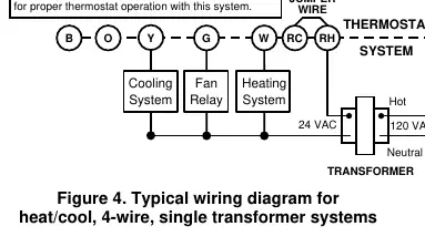
- Wiring Diagrams p. 3
- Programming p. 4, 5, 6
Table of contents
Manual images
Click an image to enlargeQuick guide from the manual
The White-Rodgers 1F80-224 is a programmable digital thermostat designed for low voltage heating and cooling systems. Before installation, ensure the power is disconnected at the main fuse box. The unit requires 2 AA alkaline batteries (included). Programming allows for four separate time/temperature settings per day. If the system does not operate, check the fuse, furnace power switch, and wiring connections.
Description and Features
This thermostat uses solid-state microcomputer technology for precise time and temperature control. Key features include:
- Simultaneous heat and cool program storage.
- Four separate time/temperature settings.
- Temporary and manual temperature hold functions.
- Fahrenheit/Celsius convertibility.
- Compressor lockout protection.
- LCD display showing setpoint, time, and room temperature.
Installation
Warning: This thermostat is for low voltage systems only. Do not use with line voltage systems.
Removing the Old Thermostat
- Shut off electricity at the main fuse box.
- Remove the front cover of the old thermostat.
- Identify each wire using the provided labels before disconnecting.
- Disconnect wires one at a time, ensuring they do not fall back into the wall.
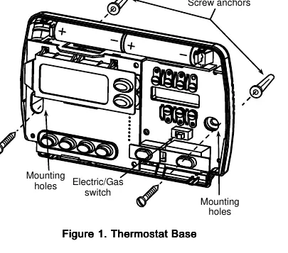
Attaching the Base
- Remove the packing material and pull the cover straight off the base.
- Connect wires to the terminal screws on the base according to the appropriate wiring schematic (see figures 2-7 in the manual).
- Place the base over the wall hole, mark mounting locations, drill holes, and fasten the base to the wall.
- Push excess wire into the wall and plug the hole with fire-resistant material to prevent drafts.
Battery Installation
The thermostat includes 2 AA alkaline batteries. You must remove the battery tag to engage the batteries. If "BATT" is displayed, replace the batteries with fresh AA alkaline batteries. Install them along the top of the base with the positive (+) end to the left.
Operation and Programming
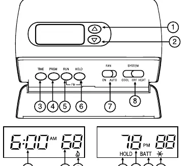
Setting the Time
- Press the TIME button once.
- Use the arrow buttons to set the hour (ensure correct AM/PM designation).
- Press TIME again and use the arrow buttons to set the minutes.
Programming Heating and Cooling
- Move the SYSTEM switch to HEAT or COOL.
- Press PRGM to view the 1st period start time and temperature.
- Use the arrow buttons to adjust the temperature.
- Press TIME to switch to time adjustment, use arrows to set the time, then press TIME again to return to temperature adjustment.
- Press PRGM to move to the next period.
- Repeat for all four periods, then press RUN.
Configuration Menu
To customize settings like cycle rate (FA/SL), backlight, or compressor lockout, press RUN, then press PRGM and RUN simultaneously. Use HOLD to advance through menu items and the arrow buttons to change settings.
Troubleshooting
- No Heat/Cool/Fan: Check fuse/breaker, furnace power switch, and door panel interlock.
- Display Blank: Replace batteries or check for power loss.
- Clock Gains/Loses Time: Check for power loss or low batteries.
- Thermostat Does Not Follow Program: Verify AM/PM settings in the program and on the clock.
Practical help
Common problems
No Heat/Cool/Fan
Check fuse/breaker, furnace power switch, and ensure the furnace blower door panel is properly installed.
Display Blank
Replace batteries or check for power loss to the system.
Clock Gains/Loses Time
Check for power loss or low batteries.
Thermostat Does Not Follow Program
Verify AM/PM settings in the program and on the clock.
Before use
- Disconnect power at the main fuse box.
- Identify wires using provided labels before disconnecting.
- Ensure system is low voltage (do not use with line voltage).
- Install 2 AA alkaline batteries.
- Remove the battery tag to engage power.
Specs in practice
- Electrical Rating
- 8 to 30 VAC 50/60 Hz or D.C.
- Setpoint Temperature Range
- 45°F to 90°F (7°C to 32°C).
- Operating Ambient Temperature
- 32°F to 105°F.
Images and diagrams
- Figure 1: Thermostat base mounting and switch locations.
- Figures 2-7: Wiring diagrams for various heating/cooling system configurations.
Model compatibility
- Compatible with standard heat/cool, electric heat, gas/oil, hydronic, and single-stage heat pump systems.
- Not compatible with multi-stage systems, systems exceeding 30 VAC/1.5 amps, or 3-wire zoned hydronic systems.

Manual page author
Emily Carter
User documentation editor
Prepares concise manual descriptions and highlights the most useful setup, operation, and maintenance information for readers.