Automotive / Motorcycle Accessories
User Manual for Rizoma License Plate Holder PTS718
Quick guide for installing the Rizoma PTS718 license plate holder. Includes step-by-step assembly instructions, wiring diagrams, and safety warnings for proper motorcycle fitment.
Table of contents
Manual images
Click an image to enlargeImportant Information
This guide provides instructions for the installation and use of the Rizoma PTS718 license plate holder. Rizoma strongly recommends that installation be performed by skilled personnel. Improper installation, repair, or maintenance can cause accidents. Always comply with local highway codes and traffic regulations.
Safety Warnings
- Compatibility: This license plate holder is not compatible with the use of side bags.
- Electrical Safety: Disconnect the battery before starting the installation of the license plate light, rear light, or turn signals. Ensure all connectors are isolated and polarity is respected. Cutting connectors or improper wiring may void the warranty and cause electrical damage or fire.
- Pre-ride Checks: After installation, check the functionality of all related components, including brakes, throttle, clutch, lights, and steering. Periodically repeat these checks, especially after long trips or prolonged periods of inactivity.
- Maintenance: Regularly inspect the product. If parts are leaking, bent, deformed, cracked, chipped, or worn, have them inspected by a Rizoma dealer before riding. Never attempt to repair or modify the product; replace with original Rizoma components.
Installation Steps
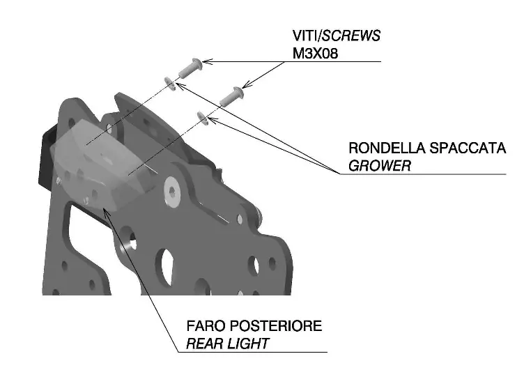
Step 1: Rear Light Installation
Secure the rear light to the support structure using the provided M3x08 screws and grower washers.
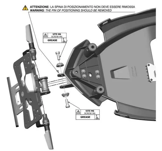
Step 2: License Plate Support
Attach the license plate holder to the support. Apply grease to the M6 screws as indicated. Ensure the positioning pin is not removed.
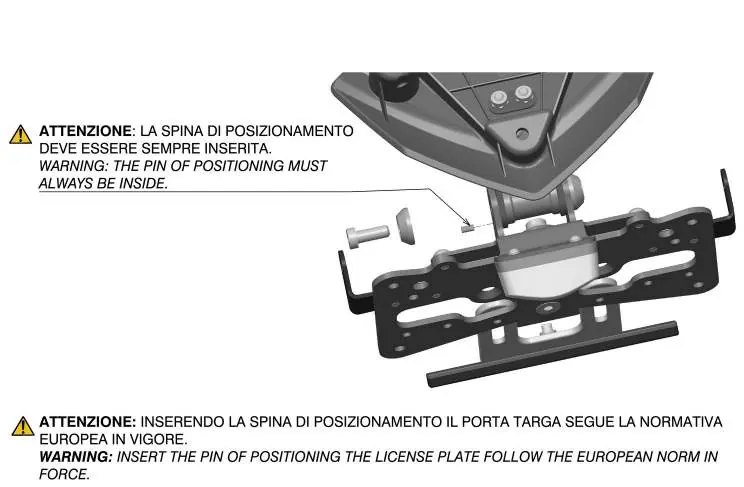
Step 3: Positioning Pin
The positioning pin must always be inserted. Inserting this pin ensures the license plate holder complies with European norms.
Step 4: Geometric Visibility
Ensure the license plate is mounted according to the geometric visibility angles (30 degrees) as specified in the diagram to comply with regulations.
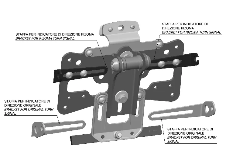
Step 5: Indicator Installation
Install the turn signal brackets. The mounting procedure is valid for both sides of the motorcycle. Use the original nuts and screws to secure the indicators.
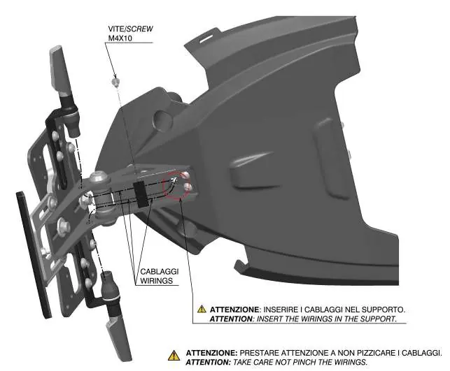
Step 6-7: Wiring and Rear Closure
Insert the wirings into the support, taking care not to pinch them. Attach the front part of the cover first, then secure it with the included screws, washers, and nuts.
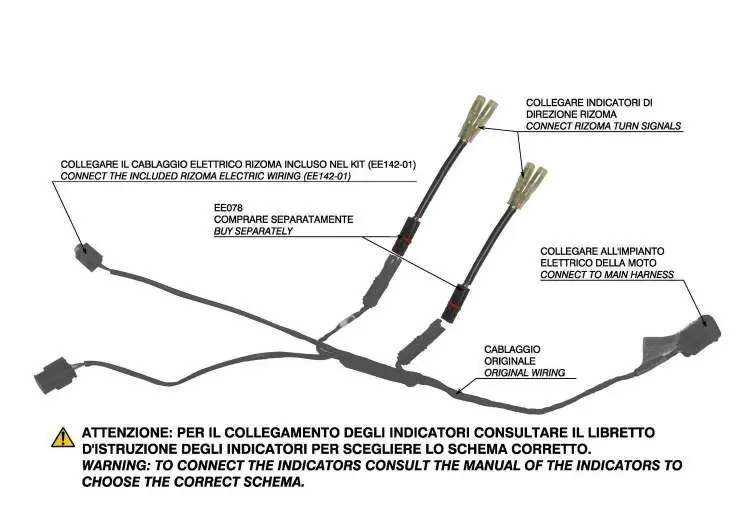
Step 8-9: Electrical Connections
Connect the rear light wires (Yellow, Black, Red) to the supplied wiring harness. For turn signals, connect the Rizoma wiring to the main harness. Consult the specific manual for your turn signals to choose the correct connection schema.
Step 10: Reflector Adjustment
Adjust the distance between the reflector and the rear wheel to avoid contact during the maximum stroke of the rear suspension. The reflector must be positioned as close as possible to the lower part of the license plate and must be perpendicular to the ground axis.
Practical help
Common problems
Incompatibility with side bags
This license plate holder is not compatible with the use of side bags.
Electrical system damage
Disconnect the battery before starting installation. Ensure all connectors are isolated and polarity is respected. Do not cut connectors.
Reflector contact with wheel
Adjust the distance between the reflector and the rear wheel to avoid contact during maximum suspension stroke.
Before use
- Verify kit completeness against the parts list.
- Ensure the motorcycle is in a stable position.
- Check that exhaust and engine temperatures are at ambient levels.
- Disconnect the battery before electrical work.
- Have necessary tools: 4mm, 3mm, 10mm, and 8mm wrenches/keys.
Images and diagrams
- Step 4 shows the required geometric visibility angles for the license plate.
- Step 8 details the wiring color codes for the rear light.
- Step 10 illustrates the required 90-degree perpendicular alignment of the reflector.
Model compatibility
- Not compatible with side bags.
- May not be approved for road circulation in countries where homologation is required.

Manual page author
Michael Turner
Technical manual editor
Reviews PDF manuals for structure, safety notes, and practical product details so readers can find the right information quickly.