Industrial / I/O Modules
Installation Instructions for Rockwell Automation 1747-SDN DeviceNet Scanner Module
A comprehensive installation and configuration guide for the Rockwell Automation 1747-SDN DeviceNet Scanner Module. This manual covers hardware installation, wiring, LED diagnostics, numeric error codes, and technical specifications.
Quick answers from the manual
Quick answer
- The 1747-SDN is a DeviceNet Scanner Module for SLC 500 systems. It requires an SLC 5/02 or later processor and specific software (RSNetWorx and RSLogix 500) for configuration. Installation involves inserting the module into the chassis and wiring the 10-pin DeviceNet connector. p. 1, 7, 9
Key actions
- Install the module in the chassis p. 9, 10
- Connect DeviceNet wiring p. 11
First start
- Turn off chassis power p. 9
- Insert module into chassis slot p. 9, 10
- Connect DeviceNet cable p. 11
Problems and fixes
Module Status LED is Flashing Green
The module is not configured. Configure the module.
p. 12
Network Status LED is Flashing Red
At least one slave device has failed to communicate. Examine the failed device.
p. 13Error codes
| Code | Meaning | Action | Pages |
|---|---|---|---|
| 70 | Module failed Duplicate Node Address check. | Change the module channel address to another available one. | p. 14 |
| 72 | Slave device stopped communicating. | Inspect the field devices and verify connections. | p. 14 |
Technical specifications
| Parameter | Value | Meaning | Pages |
|---|---|---|---|
| Operating Temperature | 0 to 60 °C | Operating range | p. 16 |
| Backplane current | 500 mA | Power consumption at 5V DC | p. 16 |
Where to find it in the PDF
- Hardware Features p. 7
- Installation p. 9, 10, 11
- LED Indicators p. 12, 13
- Numeric Codes p. 14, 15
Table of contents
Manual images
Click an image to enlargeQuick Guide from the Manual
The 1747-SDN DeviceNet Scanner Module is designed for use with SLC 500 systems. Before installation, ensure you have a personal computer with Windows 2000 or later, RSNetWorx for DeviceNet (version 2.22 or later), and RSLogix 500 software. The module must be installed in an SLC 1746 chassis with an SLC 5/02 or later processor.
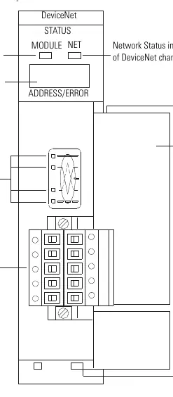
Hardware Features
The module features a front-facing access door, a 10-pin linear plug for DeviceNet connection, and status indicators. The indicators include a Module Status LED and a Network Status LED, along with a two-digit numeric display for diagnostic codes.
Installation
Follow these steps to install the module:
- Turn off the chassis power supply.
- Select a slot in the SLC 1746 chassis (any slot except the leftmost, which is reserved for the processor).
- Insert the module into the slot and apply firm, even pressure to seat it in the backplane connectors.
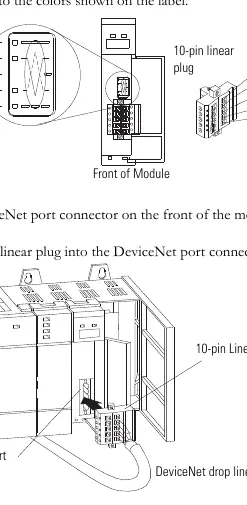
- Connect the DeviceNet drop line to the 10-pin linear plug, matching the wire colors to the label (Red: +24V, White: Can_H, Shield: Drain/Shield, Blue: Can_L, Black: +24V Return).
- Insert the plug into the DeviceNet port on the module.
LED Indicators and Troubleshooting
The module provides visual feedback via bicolor LEDs:
- Module Status (MODULE): Green indicates normal operation. Flashing green means the module is not configured. Flashing red indicates invalid configuration. Solid red indicates an unrecoverable fault.
- Network Status (NET): Green indicates normal communication. Flashing green means the channel is enabled but no communication is occurring. Flashing red indicates a slave device communication failure.
The numeric display flashes diagnostic codes at 1-second intervals. Common codes include:
- 0-63: Normal operation (node address).
- 70: Duplicate Node Address check failed.
- 72: Slave device stopped communicating.
- 73: Identity mismatch (electronic key).
- 91: Bus-off condition detected.
Technical Specifications
The module operates in a Pollution Degree 2 industrial environment. Power requirements are 5V DC (500 mA) from the backplane and 24V DC (90 mA) for DeviceNet. Operating temperature range is 0 to 60 °C (32 to 140 °F).
Practical help
Common problems
Module Status LED is Off
Verify power connections and ensure power is applied to the module.
Module Status LED is Flashing Red
Invalid configuration detected. Check the configuration setup.
Module Status LED is Solid Red
Unrecoverable fault. Replace the module.
Numeric code 70 displayed
Duplicate Node Address. Change the module channel address to an available one.
Numeric code 91 displayed
Bus-off condition. Check DeviceNet connections and physical media integrity.
Before use
- Ensure SLC 1746 chassis with SLC 5/02 or later processor is available.
- Install RSNetWorx for DeviceNet software (version 2.22 or later).
- Install RSLogix 500 software.
- Verify power supply is turned off before installation.
- Ensure proper grounding for electrostatic discharge protection.
Specs in practice
- Backplane current
- 5V DC, 500 mA
- DeviceNet power
- 24V DC, 90 mA Class 2
- Operating Temperature
- 0 to 60 °C (32 to 140 °F)
Images and diagrams
- Hardware features diagram identifying status indicators and wiring port.
- Wiring diagram showing the 10-pin linear plug connection to the DeviceNet drop line.
Model compatibility
- Requires SLC 5/02 or later processor.
- Not compatible with 1747-ASB adapter module in remote I/O chassis.
- Requires latest EDS file for RSLinx Classic and RSNetWorx.

Manual page author
Emily Carter
User documentation editor
Prepares concise manual descriptions and highlights the most useful setup, operation, and maintenance information for readers.