Industrial / Communication Modules
User Manual for ArmorBlock 16-Channel IO-Link Hubs
Quick guide for ArmorBlock 16-Channel IO-Link Hubs (1732IL-IB16M12, 1732IL-10X6M12, 1732IL-16CFGM12M12L). Learn about installation, configuration, wiring, and diagnostic status indicators.
Table of contents
Manual images
Click an image to enlargeQuick guide from the manual
The ArmorBlock 16-Channel IO-Link hubs are designed to connect sensors and actuators to an IO-Link master, providing additional I/O capacity in industrial environments. This manual covers the configuration, operation, and troubleshooting of the 1732IL-IB16M12, 1732IL-10X6M12, and 1732IL-16CFGM12M12L models.
Module Overview
These hubs feature a sealed die-cast zinc housing suitable for tough industrial environments. They utilize M12 connectors for I/O signals and the IO-Link interface. The hubs receive binary signals and transfer them to the controller via the IO-Link master.
- 1732IL-IB16M12: 16 digital inputs.
- 1732IL-10X6M12: 10 digital inputs and 6 digital outputs.
- 1732IL-16CFGM12M12L: 16 configurable digital inputs/outputs.
Configuration
Configuration is performed using the Studio 5000 Logix Designer environment. You must use RSLogix 5000 or Studio 5000 (version 20 or later) to configure these hubs. You can configure parameters via the Add-on Profile (AOP) or by using CIP message instructions for advanced settings.
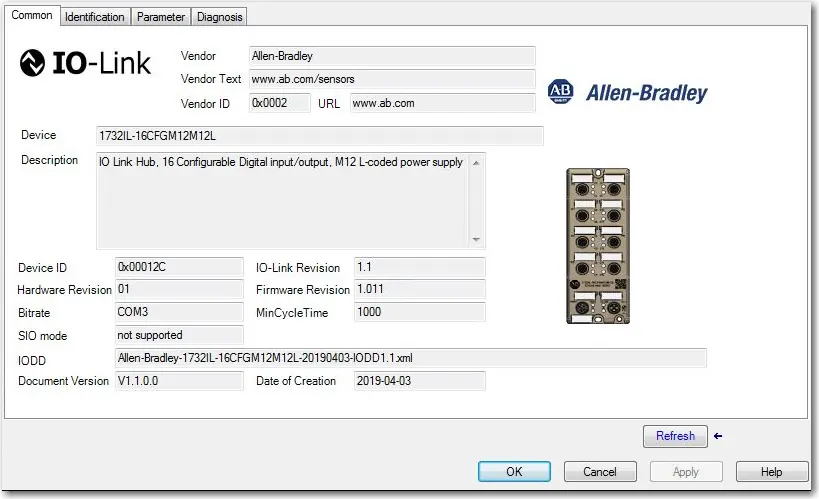
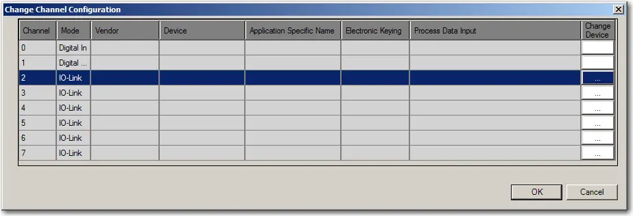
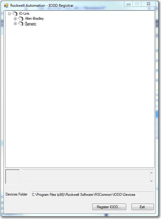
To register an IODD file, right-click the IO-Link channel in the channel tree, select Register IODD, and locate the appropriate XML file. Ensure you have administrator rights on the machine where the Add-on Profile is installed.
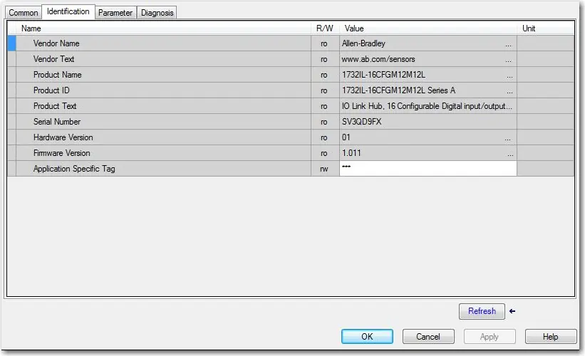
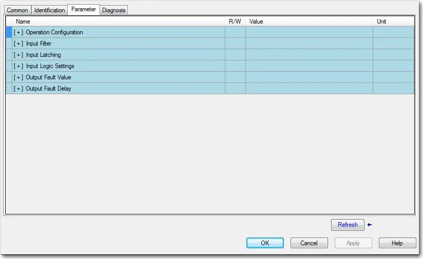
Parameters
Various parameters can be configured to optimize performance:
- Input Filter: Specifies the filter time for module inputs (default 3 ms).
- Input Latching: Sets the minimum time an input stays in one state.
- Input Logic Settings: Determines if inputs are Normally Open (NO) or Normally Closed (NC).
- Output Fault Values: Configures output behavior during communication loss (available on 1732IL-10X6M12 and 1732IL-16CFGM12M12L).
- Output Fault Delay: Sets the delay before monitoring output for faults.
Diagnostics
The hubs provide diagnostic messages to identify device status. You can view these in the Diagnosis tab of the AOP. Status indicators on the device provide visual feedback:
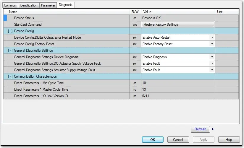
- IO-Link Status: Indicates communication state (Flashing green = running, Red = fault).
- Power Supply Status: Indicates if power is operating normally (Green) or low (Red, <18V).
- Diagnostic Status: Red indicates module diagnosis is available.
Wiring
The hubs use M12 connectors. Ensure proper wiring according to the specific pinout diagrams provided in the manual. The system supports standard unshielded connection cables for communication between masters and hubs.
Practical help
Common problems
Hardware fault indicator is red
Check for short-circuits, overloads, or communication errors. Consult the event codes in the manual.
Power supply indicator is red
Verify that the sensor or actuator power supply voltage is not below 18V.
Cannot configure parameters in AOP
Ensure you are using the correct AOP version (1732 AOP v3.1.xx or later) or use CIP message instructions.
Before use
- Ensure you have Studio 5000 Logix Designer version 20 or later.
- Verify the IO-Link master is compatible with the hub.
- Download the correct IODD file from the Rockwell Automation PCDC or IO-Link community.
- Ensure power supply is within the required operating range (18V+).
- Confirm all M12 connections are secure.
Specs in practice
- Input Filter
- Configures debounce time for inputs to prevent noise (default 3ms).
- Input Latching
- Sets the minimum time an input must remain in a state before switching.
- Output Fault Value
- Determines if outputs turn Off or On during communication loss.
Images and diagrams
- Status Indicators: Located on the front panel to show IO-Link, power, and channel status.
- Wiring Diagrams: Show pinouts for M12 connectors connecting the hub to the IO-Link master.
Model compatibility
- Requires RSLogix 5000 or Studio 5000 version 20 or later.
- IODD files must be based on IO-Link specification v1.0.1 or v1.1.

Manual page author
Michael Turner
Technical manual editor
Reviews PDF manuals for structure, safety notes, and practical product details so readers can find the right information quickly.