Industrial / I/O Modules
User Manual for Unitronics IO-Link HUB 1616P-M2P6
Get started with the Unitronics IO-Link HUB 1616P-M2P6. This guide covers installation, wiring diagrams, LED status definitions, and technical specifications for this IP67-rated industrial I/O module.
Table of contents
Manual images
Click an image to enlargeQuick Guide from the Manual
The Unitronics ULK-1616P-M2P6 is an IO-Link master station designed for industrial environments. It serves as a bridge between IO-Link devices and automation systems. Key safety requirements include using a limited power source with overvoltage and overcurrent protection. Do not use AC power, as it poses a risk of rupture and equipment damage.
Product Overview
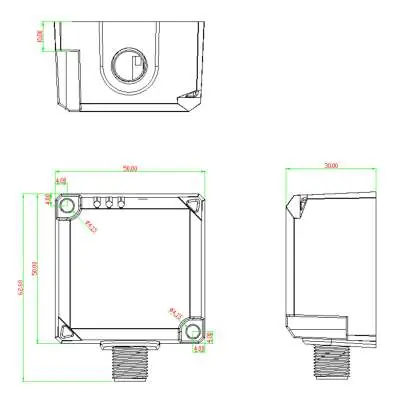
This module features a compact structure with an IP67 protection level, making it suitable for demanding application environments. It is designed for use in automated lines and can be installed in control cabinets or directly on-site as a remote I/O.
Technical Specifications
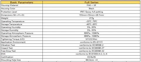
The device operates within a voltage range of 18-30 VDC. It features a robust housing (PA6 + GF) and is rated for temperatures between -25°C and 70°C. The module dimensions are 155mm x 53mm x 28.7mm.
Installation
Proper installation is critical for system longevity and performance:

- Site Selection: Avoid installing near devices with high heat dissipation (heaters, transformers) or sources of strong electromagnetic interference (large motors, frequency converters).
- Spacing: Maintain a distance of more than 20mm between modules to ensure adequate heat dissipation.
- Cabling: Do not bend cables within a radius of 40mm to prevent disconnection.
- Wiring: Ensure wiring is correct to avoid burnout.
Hardware Interface & Wiring
The module uses M12 connectors for both power and I/O signals.
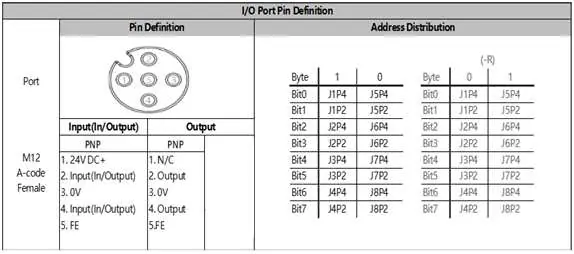
- Power Port: Uses a 5-pin M12 A-coded male connector. Pin 1 is V+, Pin 2 is Output P24V, Pin 3 is 0V, and Pin 4 is C/Q.
- I/O Port: Uses a 5-pin M12 A-coded female connector. Pin 1 is 24VDC+, Pin 2 and 4 are Input/Output signals, Pin 3 is 0V, and Pin 5 is FE (Functional Earth).
LED Status Indicators
The module provides visual feedback via LEDs:
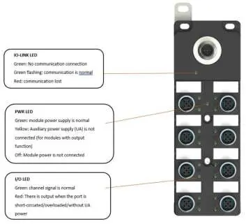
- PWR LED: Green indicates power is OK. Yellow indicates no UA power (check +24V on pin 2). Off indicates no power.
- LINK LED: Green flashing indicates normal communication. Red indicates interrupted communication with the master station. Off indicates no link.
- IO LED: Green indicates normal channel signal. Red indicates a short circuit, overload, or lack of UA power on the port.
Practical help
Common problems
Link indicator is off
Check the cable connection and ensure the master station is functioning correctly.
PWR indicator is yellow
This indicates no UA power. Check if +24V is present on pin 2 of the power connector.
IO indicator is red
This indicates a port short-circuit, overload, or missing UA power. Verify wiring and measure UA voltage.
Module not powered
Check the power wiring and ensure the power supply is active.
Before use
- Ensure the power supply has overvoltage and overcurrent protection.
- Verify that ambient conditions comply with the specified temperature and humidity ranges.
- Check for sources of electromagnetic interference near the installation site.
- Ensure a minimum spacing of 20mm between adjacent modules.
- Verify that all cables are not bent beyond a 40mm radius.
- Confirm that the power source is DC, not AC.
Images and diagrams
- Wiring diagrams illustrate the pinout connections for output and input/output signals.
- LED status tables provide troubleshooting steps based on the color and state of the indicators.
Model compatibility
- Designed for industrial environments and automated lines.
- Not compatible with AC power sources.
- IP rating is not part of UL certification.

Manual page author
Emily Carter
User documentation editor
Prepares concise manual descriptions and highlights the most useful setup, operation, and maintenance information for readers.