Plumbing / Toilet Flushers
Electronic Flushing System SANELA SLW 10NK / SLW 10NKX User Manual
Quick guide for the SANELA SLW 10NK and SLW 10NKX electronic flushing system. Includes installation steps, sensor range settings, water flow adjustment, and electrical connection instructions.
Table of contents
Manual images
Click an image to enlargeQuick Guide
The SANELA SLW 10NK and SLW 10NKX are electronic flushing systems designed for wall-mounted toilets. Important: The unit must be kept under constant voltage for proper function. Do not connect the power supply unit behind a light switch or any switch that cuts power to the circuit.
Key Parameters:
- Power Supply: 24 V DC
- Sensor Range: 0.3 - 0.7 m
- Water Pressure: 0.15 - 0.6 MPa
- Sieve Dimension: ≤ 90 µm
Installation
The installation process involves mounting the flushing unit into the wall and connecting the water supply and electrical components. Ensure you have read the attached safety instructions before beginning.
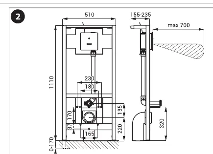
- Follow the mounting instructions provided in the manual for your specific toilet type (ceramic or stainless steel).
- Use the provided mounting template and hardware to secure the unit.
- Ensure the water supply is connected correctly and the sieve is installed to prevent debris from entering the valve.
- The system requires a 24V DC power connection.
Settings and Adjustments
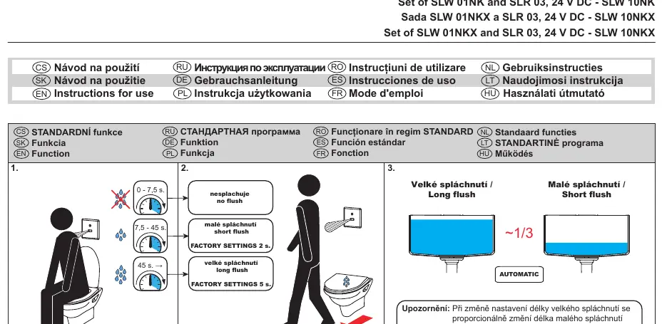
The system comes with factory settings, but parameters can be adjusted using the SANELA Control application or the SLD 03 remote control.
- Factory Settings: Short flush (2s), Long flush (5s).
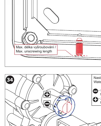
- Water Flow Adjustment: The flow can be adjusted manually on the valve. Turn the adjustment screw to reduce or increase the flow as needed.
- Sensor Range: The sensor range is factory-set but can be adjusted if necessary.
Electrical Connection
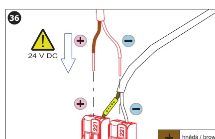
The unit requires a constant 24V DC power supply. Connect the brown wire to the positive (+) terminal and the white wire to the negative (-) terminal. Do not connect the power supply to a switched circuit, as the unit requires constant power to operate correctly.
Maintenance
Regular maintenance is recommended to ensure the longevity of the system. Check the water supply sieve periodically for debris. If the system is not functioning correctly, verify the power supply and ensure the sensor is not obstructed.
Manufacturer information
SANELA spol. s r. o.
Practical help
Common problems
System does not flush
Check if the unit is receiving constant 24V DC power. Ensure the power supply is not connected to a light switch.
Water flow is too high or too low
Adjust the water flow using the adjustment screw on the valve (turn to + for increase, - for reduction).
Sensor not detecting user
Verify the sensor range (0.3 - 0.7 m) and ensure there are no obstructions in front of the sensor.
Before use
- Verify water pressure is between 0.15 and 0.6 MPa.
- Ensure the sieve is installed (dimension ≤ 90 µm).
- Confirm 24V DC power supply is available and constant.
- Ensure the power supply is not connected to a light switch.
- Check that the toilet type (ceramic or stainless steel) matches the installation steps.
Specs in practice
- 0.15 - 0.6 MPa
- The required water pressure range for the flushing mechanism to operate correctly.
Images and diagrams
- The wiring diagram on page 7 shows the connection of the 24V DC power supply (brown to +, white to -).
- The water flow adjustment diagram on page 7 illustrates the screw used to increase or decrease flow.
- Installation steps on pages 4-6 detail the specific mounting requirements for ceramic versus stainless steel toilets.
Model compatibility
- Compatible with ceramic and stainless steel toilets (specific installation steps apply).
- Requires external power supply (e.g., SLZ 01Y, SLZ 04Y) for operation.
- Parameters can be configured using the SLD 03 remote control.

Manual page author
Michael Turner
Technical manual editor
Reviews PDF manuals for structure, safety notes, and practical product details so readers can find the right information quickly.