Electronics / Sim Racing Equipment
Installation Guide for Sanwa 150-SNCRC2 Racing Simulator Cockpit
Complete assembly and installation guide for the Sanwa 150-SNCRC2 Racing Simulator Cockpit. Includes step-by-step instructions for frame assembly, seat mounting, and pedal/steering wheel adjustments.
Table of contents
Manual images
Click an image to enlargeQuick guide from the manual
This document provides assembly instructions for the Sanwa 150-SNCRC2 Racing Simulator Cockpit. Before beginning, ensure you have all parts listed in the inventory. The seat is rated for a maximum weight of 100kg (220lbs), and the gear shifter mount is rated for 10kg (22lbs). Always ensure the floor surface is level and all screws are fully tightened before use.
Parts List
The package includes various frame components (A-L), seat (M), mounting brackets (N-P), adjustment feet (Q), seat rails (R), and various hardware including screws (P-A to P-F) and tools (Z, A1). Verify all components against the diagram on page 2 before starting assembly.
Assembly Steps
Frame Assembly:
- Step 1: Assemble the base frame using part A and adjustment feet Q.
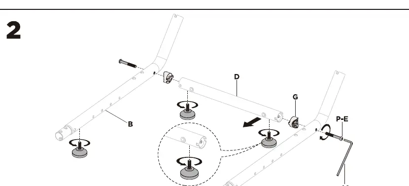
- Step 2: Connect the frame sections B and D using screws P-E and G. Do not fully tighten screws until the frame is aligned.
- Step 3: Secure the frame connections using screws P-E.
- Step 4-5: Continue assembling the main frame structure using screws P-B and the provided hex key.
Mounting Adjustments:
- Step 6: Attach the pedal mount. The tilt can be adjusted to 0, 15, or 27 degrees.
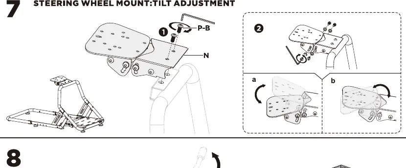
- Step 7: Install the steering wheel mount. The tilt angle is adjustable.
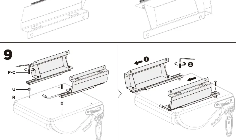
- Step 8-9: Assemble the seat rails (R) and attach them to the seat using screws P-C and U.
- Step 10-11: Mount the seat onto the main frame using screws P-B.
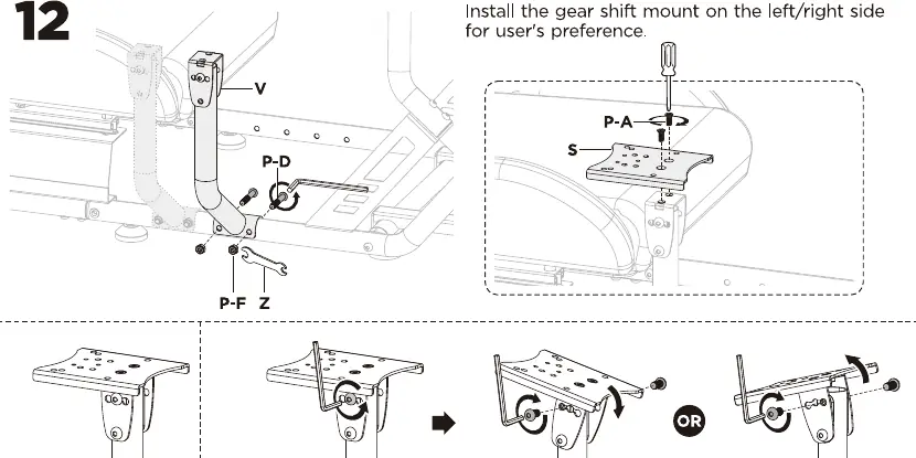
- Step 12: Install the gear shifter mount (V) on either the left or right side according to your preference.
- Step 13: Final adjustments for seat position, steering wheel tilt, and pedal angle.
Maintenance
Check the stability of the cockpit and tighten all screws at regular intervals (at least every three months) to ensure safe operation.
Practical help
Common problems
Frame instability or wobbling
Ensure all screws are fully tightened after the initial assembly and check them periodically every three months.
Difficulty adjusting seat or mounts
Ensure the screws are loosened sufficiently before attempting to tilt or slide the components, then re-tighten securely.
Before use
- Verify all parts are present according to the parts list on page 2.
- Ensure the floor surface is level.
- Check that the seat is securely fastened to the frame.
- Confirm the steering wheel and pedal mounts are tightened to the desired angle.
- Verify the gear shifter mount is securely attached to the preferred side.
Specs in practice
- Seat Weight Limit
- 100kg / 220lbs maximum load capacity.
- Gear Shifter Weight Limit
- 10kg / 22lbs maximum load capacity.
Images and diagrams
- Steps 1-5: Base frame assembly and connection.
- Step 6: Pedal mount tilt adjustment (0, 15, 27 degrees).
- Step 7: Steering wheel mount tilt adjustment.
- Step 12: Gear shifter mount installation (left/right side).
Model compatibility
- The gear shifter mount can be installed on either the left or right side of the cockpit.

Manual page author
Michael Turner
Technical manual editor
Reviews PDF manuals for structure, safety notes, and practical product details so readers can find the right information quickly.