Tools / Automotive Tools
User Manual for Sealey AP1100M Mobile Workbench
Comprehensive user guide for the Sealey AP1100M 2-Level Mobile Workbench. Includes assembly instructions, safety guidelines, technical specifications, and maintenance tips.
Quick answers from the manual
Quick answer
- The Sealey AP1100M is a 2-level mobile workbench with a 300kg capacity. Assembly requires two people and involves attaching leg frames, brackets, castors, and a shelf to the bench top. p. 1, 2
Key actions
- Assemble the bench by loosely tightening all bolts first, then fully tightening them after the unit is assembled. p. 2
First start
- Place the bench on level, solid ground and apply the brakes to the locking castors before use. p. 1
Maintenance and reset
- Keep the bench clean and tidy in accordance with good workshop practice. Do not use solvents that may damage the paint surface. p. 1
Technical specifications
| Parameter | Value | Meaning | Pages |
|---|---|---|---|
| Capacity | 300kg | Maximum load capacity | p. 1 |
| Nett Weight | 59.30kg | Weight of the unit | p. 1 |
Where to find it in the PDF
- Safety, Introduction, Specification, and Assembly Diagram p. 1
- Assembly Steps p. 2
Table of contents
Manual images
Click an image to enlargeImportant Information
The Sealey AP1100M is a sturdy, 2-level mobile workbench designed for workshop use. It features a 300kg capacity and includes two fixed castors, two locking castors, and a heavy-duty handle. Assembly requires two people due to the weight of the unit.
Safety Instructions
- Grounding: Always use the bench on level, solid ground, preferably concrete. Avoid tarmacadam as the bench may sink.
- Stability: Always apply the brakes to the locking castors before using the bench.
- Work Area: Keep the area clean, uncluttered, and well-lit. Keep children and unauthorized persons away.
- Usage: Do not use the bench outside, in wet/damp locations, or areas with condensation.
- Loads: Do not place heavy loads on the lower shelf.
- Workpiece Security: Do not carry out work without the workpiece being adequately secured. Use clamps or a vice (not included).
- Maintenance: Do not clean the bench with solvents that may damage the paint surface.
Technical Specifications
- Model No: AP1100M
- Capacity: 300kg
- Nett Weight: 59.30kg
- Size (inc. Handle): 1180 x 700 x 830mm
- Work Surface: 1100 x 700mm
Assembly Instructions
Important: Loosely tighten all bolts during assembly; once the entire unit is assembled, fully tighten all bolts.
- Place the bench top upside down on the floor, using a floor covering to protect the surface.
- Fasten the four support brackets to the leg frames using the provided fixings.
- Fasten the leg/bracket assemblies to the channels welded to the underside of the bench top.
- Fasten the four castor brackets to the legs.
- Fasten the two locking castors to the legs at one end.
- Fasten the two fixed castors to the legs at the other end.
- Fasten the shelf to the crossmembers of the leg frames.
- Using two people, turn the bench the right way up.
- Fix the handle to the end of the bench where the locking castors are fitted.
Manufacturer information
Sealey Group
Practical help
Common problems
Bench feels unstable or sinks into the ground
Ensure the bench is placed on level, solid ground, preferably concrete. Avoid tarmacadam surfaces.
Difficulty aligning parts during assembly
Keep all bolts loosely tightened during the assembly process. Only fully tighten all bolts once the entire unit is assembled.
Before use
- Ensure the bench is on level, solid ground.
- Apply the brakes to the locking castors.
- Ensure the work area is clean and well-lit.
- Secure the workpiece using clamps or a vice.
- Verify that no heavy loads are placed on the lower shelf.
Specs in practice
- Work Surface
- The usable area on top of the bench is 1100 x 700mm.
Images and diagrams
- FIG.1: Exploded view showing the assembly sequence of the bench top, leg frames, brackets, castors, shelf, and handle.
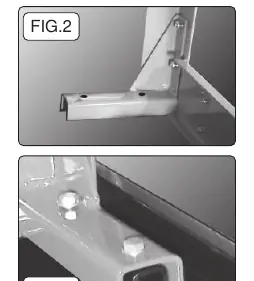
- FIG.2: Detail view showing how to fasten support brackets to the leg frames.
- FIG.3: Detail view showing how to fasten the leg/bracket assembly to the bench top channels.

Manual page author
David Miller
Documentation analyst
Organizes user manual content into clear summaries, with attention to model details, product context, and everyday usability.