Tools / Air Tools Painting
Sealey HVLP05 Premier Professional Gravity Feed Spray Gun Parts List
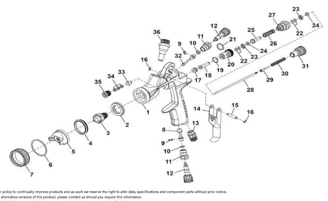
View the exploded parts diagram and detailed component list for the Sealey HVLP05 Premier Professional Gravity Feed Spray Gun. Identify replacement parts and assembly order.
Table of contents
Quick guide from the manual
This document provides the official parts information for the Sealey HVLP05 Premier Professional Gravity Feed Spray Gun. It includes an exploded view diagram to assist with assembly and disassembly, alongside a comprehensive list of component part numbers required for maintenance and repairs.
Exploded view and parts identification
The exploded diagram illustrates the internal and external components of the spray gun. Each part is numbered, corresponding to the item numbers in the parts list. Use this diagram to understand the correct assembly sequence of the air valve, fluid needle, and nozzle components.
Component list
The parts list details all 36 standard components of the HVLP05 spray gun. Key components include:
- Gun Body (1)
- Fluid Nozzle (3)
- Air Cap (5)
- Trigger (14)
- Fluid Needle (28)
When ordering spare parts, always reference the specific part number (e.g., HVLP05-01) rather than just the item number.
Optional parts and configurations
The spray gun supports different nozzle setups. While the standard configuration is 1.3mm, the following optional sets are compatible:
- 1.2mm Set-Up: Includes Fluid Nozzle (03A), Air Cap (05A), and Fluid Needle (28A).
- 1.4mm Set-Up: Includes Fluid Nozzle (03B), Air Cap (05B), and Fluid Needle (28B).
Ensure that any spare parts are fitted by a competent person to maintain the integrity of the tool.
Manufacturer information
Sealey Group
Practical help
Common problems
Need to replace a worn fluid nozzle
Identify the correct part number from the list (e.g., HVLP05-03 for 1.3mm) and ensure the matching needle and air cap are used.
Air leakage around the trigger
Inspect the Air Valve Shaft (17) and Air Valve Seals (18, 20) for wear or damage.
Before use
- Verify the model number is HVLP05.
- Ensure the air supply is disconnected before attempting any disassembly.
- Use the exploded diagram to confirm the correct order of assembly for the air valve and needle components.
- Check if the current nozzle size (1.3mm) is appropriate for the paint viscosity being used.
Images and diagrams
- The diagram shows the exploded view of the spray gun, allowing you to see how the trigger, air valve, and fluid needle mechanisms fit together.
- Numbers in the diagram correspond directly to the 'Item' column in the parts list table.
Model compatibility
- The unit is compatible with optional 1.2mm and 1.4mm nozzle sets.
- Spare parts must be fitted by a competent person.

Manual page author
Michael Turner
Technical manual editor
Reviews PDF manuals for structure, safety notes, and practical product details so readers can find the right information quickly.