Furniture / Storage Cabinets
Sealey Racking Unit AP6150.V3 & AP6150GS.V3 User Manual
Quick guide for the Sealey Racking Unit (AP6150.V3 & AP6150GS.V3). Includes assembly instructions, safety warnings, specifications, and parts list.
Table of contents
Manual images
Click an image to enlargeQuick guide from the manual
This document provides assembly and safety instructions for the Sealey Racking Unit (AP6150.V3 and AP6150GS.V3). The unit features a steel/galvanised frame with five MDF shelves and is designed for easy, clip-together assembly without nuts and bolts. The uprights are in two pieces, allowing the unit to be used as a single tall bay or split into two separate shelf systems.
Safety instructions
- Surface: Always erect the rack on a level and solid surface, such as concrete.
- Load Limits: The maximum load for each shelf is 150kg. Heavier items should be placed on the lower shelves and distributed evenly.
- Usage: Do not use the rack for any purpose other than its intended design. Do not use outdoors, in damp/wet locations, or areas with condensation.
- Installation: Where possible, fix the rack to the wall using suitable fixings. Ensure the rack is properly assembled before loading.
- Maintenance: Do not clean shelf supports with solvents that may damage the surface.
Specifications
- Model No: AP6150.V3 (Painted) / AP6150GS.V3 (Galvanised)
- Dimensions: 1800mm (Height) x 800mm (Width) x 300mm (Depth)
- Weight: 11kg
- Capacity: 150kg per shelf (750kg total per rack)
Contents
Before assembly, unpack the product and verify all parts are present:
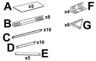
- A: Shelves (x5)
- B: Uprights (x8)
- C: Horizontal supports (x10)
- D: Horizontal supports (x10)
- E: Shelf supports (x5)
- F: Joining pieces (x4)
- G: Feet (x8)
Assembly
Step 1: Decide on the height of the lowest shelf. Use a shelf to support the uprights (B). Refer to Step 1B for detailed connection instructions.
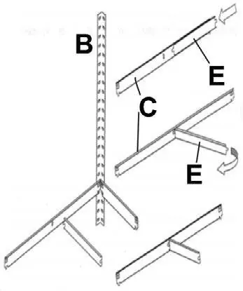
Step 1B: Use a soft hammer or mallet to tap down horizontal supports. Use a screwdriver to bend the tabs down to secure the connection.
Step 2: Build the ends first by joining the B sections together. Refer to Step 2B for joining pieces.
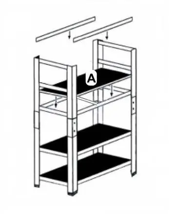
Step 3: Fit the shelves and the remaining C and E pieces.
Step 4: Fit the final shelf.
Maintenance and disposal
Recycle unwanted materials instead of disposing of them as waste. Sort all tools, accessories, and packaging for recycling. When the product is unserviceable, dispose of it according to local regulations.
Manufacturer information
Sealey Group
Practical help
Common problems
Rack instability
Ensure the rack is erected on a level, solid surface (e.g., concrete) and fixed to the wall with suitable fixings.
Difficulty securing supports
Use a soft hammer or mallet to tap down horizontal supports and a screwdriver to bend the tabs down.
Before use
- Check all parts against the contents list (A-G)
- Ensure the floor area is level and solid
- Wear protective gloves during assembly
- Verify the load does not exceed 150kg per shelf
- Ensure the area is clear and well-lit
Specs in practice
- Max load per shelf
- 150kg
- Total capacity
- 750kg per rack
Images and diagrams
- Step 1: Initial frame setup using uprights B and shelf supports.
- Step 1B: Technique for securing supports using a mallet and screwdriver.
- Step 2: Joining upright sections B using joining pieces F.
- Step 3 & 4: Final assembly of shelves and remaining supports.
Model compatibility
- Two-piece uprights allow the unit to be used as a single bay rack or split into two separate shelf systems.

Manual page author
David Miller
Documentation analyst
Organizes user manual content into clear summaries, with attention to model details, product context, and everyday usability.