Furniture / Storage Cabinets
Sealey 1.52M Woodworking Bench with 4 Drawers AP1640
Assembly and safety guide for the Sealey 1.52M Woodworking Bench (AP1640). This manual provides a complete parts list, step-by-step assembly instructions, and essential safety precautions for proper setup and maintenance.
Table of contents
Manual images
Click an image to enlargeQuick guide from the manual
This manual provides instructions for assembling the Sealey 1.52M Woodworking Bench (AP1640). The assembly process involves 14 steps, requiring basic tools and careful alignment of parts. Ensure the bench is placed on level, solid ground, preferably concrete, before use.
Safety
- Ensure Health & Safety and local workshop regulations are followed.
- Use the bench only on level, solid ground.
- Keep the work area clean, uncluttered, and well-lit.
- Keep children and unauthorized persons away from the work area.
- Do not use the bench outdoors or in damp/wet locations.
- Do not clean the bench with solvents that may damage the surface.
- Always secure the workpiece adequately before starting work.
Specifications
- Model No: AP1640
- Overall Size (W x D x H): 1520mm x 620mm x 820mm
- Worktop: 1520mm x 500mm
- Tool Well: 1110mm x 410mm
- Drawer (x4): 460mm x 390mm x 80mm
- Vice (x1): 280mm wide x 180mm opening
Parts List
The bench is supplied with the following components:
- Table top, Shelf, Cross braces (2), Legs (2), Vice, Sliding partition, Lower supports (2).
- Drawer components: Front panels, Back panels, Side panels, Bottoms, Handles.
- Hardware: Screws (60mm, 30mm, 35mm, 40mm), Bolts (90mm), Connecting nuts, Washers, Hex wrench, Wood pegs, Anvil pegs.
Assembly Instructions
Steps 1-4: Frame Assembly
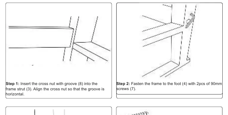
- Insert the cross nut with groove (8) into the frame strut (3), ensuring the groove is horizontal.
- Fasten the frame to the foot (4) using 90mm screws (7).
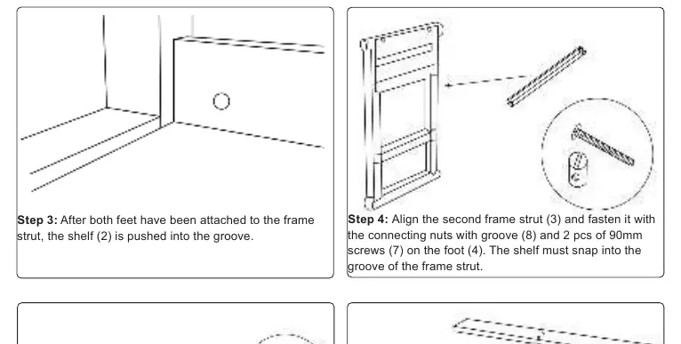
- After attaching both feet, push the shelf (2) into the groove.
- Align the second frame strut (3) and fasten it with connecting nuts (8) and 90mm screws (7). Ensure the shelf snaps into the groove.
Steps 5-8: Support and Worktop
- Attach the lower support (16) to the front with 35mm screws (14).
- Attach the lower support (16) to the partition wall with rails (15) using 35mm screws (14).
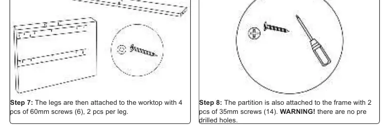
- Attach the legs to the worktop using 60mm screws (6).
- Attach the partition to the frame with 35mm screws (14). Note: There are no pre-drilled holes for this step.
Steps 9-14: Drawers and Finishing
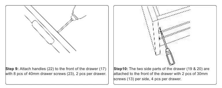
- Assemble drawers by attaching handles (22) to the front (17) with 40mm screws (23).
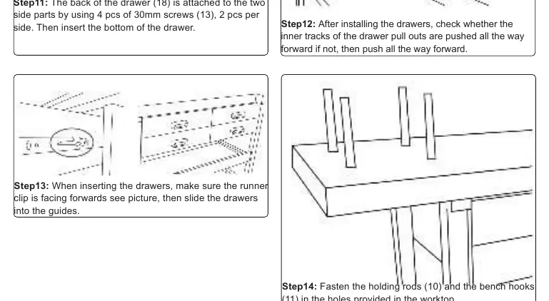
- Attach side parts (19 & 20) to the front using 30mm screws (13).
- Attach the back (18) to the sides using 30mm screws (13) and insert the drawer bottom.
- Check that inner tracks are pushed forward. Insert drawers ensuring the runner clip faces forward.
- Fasten holding rods (10) and bench hooks (11) into the worktop holes.
Maintenance and Environment
Recycle unwanted materials instead of disposing of them as waste. All tools, accessories, and packaging should be sorted and taken to a recycling center. The product is covered by a 12-month guarantee from the date of purchase.
Manufacturer information
Sealey Group
Practical help
Common problems
Drawer sticking or not sliding correctly
Check if the inner tracks of the drawer pull-outs are pushed all the way forward. If not, push them forward before inserting the drawer.
Difficulty attaching partition (Step 8)
Note that there are no pre-drilled holes for this step; you will need to secure the partition manually.
Assembly alignment issues
Ensure the cross nut with groove (8) is aligned horizontally when inserting into the frame strut.
Before use
- Ensure the work area is clean, uncluttered, and well-lit.
- Verify the bench is placed on level, solid ground (preferably concrete).
- Check that all parts listed in the contents are present.
- Ensure the workpiece is adequately secured before starting work.
- Verify all screws and bolts are tightened securely.
Specs in practice
- Overall Size
- 1520mm x 620mm x 820mm (Width x Depth x Height)
Images and diagrams
- The parts diagram on page 1 identifies all components by number for easy reference during assembly.
- Assembly steps 1-6 on page 2 detail the frame and support structure construction.
- Assembly steps 7-14 on page 3 detail the worktop attachment and drawer assembly.
Model compatibility
- For indoor use only.
- Do not use in damp or wet locations.
- Do not use solvents for cleaning.

Manual page author
Michael Turner
Technical manual editor
Reviews PDF manuals for structure, safety notes, and practical product details so readers can find the right information quickly.