HVAC / Thermostats & Controls
Sears 1F80-382 Programmable Electronic Digital Thermostat
Quick guide for the Sears 1F80-382 programmable digital thermostat. Learn how to install, wire, program heating and cooling schedules, and troubleshoot common issues.
Quick answers from the manual
Quick answer
- The 1F80-382 is a programmable digital thermostat for low-voltage heating and cooling systems. It supports 5-day/1-day/1-day programming and requires 2 AA batteries. p. 1
Key actions
- Programming Schedules p. 6
- Resetting the Thermostat p. 7
First start
- Remove the battery tag, mount the base, connect wires according to the diagram, and set the current time/day. p. 2, 6
Problems and fixes
No Heat/No Cool
Check fuse/breaker, ensure system switch is set correctly, verify wiring, and check if the furnace requires service.
p. 7Maintenance and reset
- Reset the thermostat by pressing the up arrow, down arrow, and TIME button simultaneously. p. 7
Technical specifications
| Parameter | Value | Meaning | Pages |
|---|---|---|---|
| Electrical Rating | 8 to 30 VAC 50/60 Hz or D.C. | Operating voltage range. | p. 1 |
| Max Load | 1.5 Amps | Maximum total load for all terminals combined. | p. 1 |
Where to find it in the PDF
- Installation p. 2
- Wiring Diagrams p. 3
- Operation p. 4
- Troubleshooting p. 7, 8
Table of contents
Manual images
Click an image to enlargeQuick Guide
The Sears 1F80-382 is a programmable digital thermostat designed for low-voltage heating and cooling systems. It features 5-day/1-day/1-day programming, a backlit display, and battery-powered operation. Before installation, ensure your system is compatible (low voltage, not exceeding 30 VAC/1.5 amps). Always disconnect power at the main fuse box before beginning installation.
Installation
Removing Old Thermostat: Shut off electricity at the main fuse box. Remove the front cover of the old thermostat, label each wire as you disconnect it, and ensure wires do not fall back into the wall.
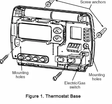
Mounting: Remove the packing material from the new thermostat. Pull the cover straight off the base. Place the base over the hole in the wall, mark the mounting holes, drill, and fasten the base to the wall using the provided screws. Use a level to ensure it is straight.
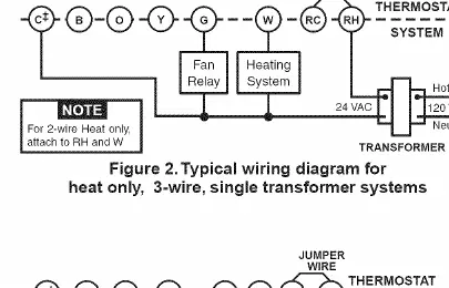
Wiring: Connect wires to the terminal screws on the base according to the specific wiring schematic for your system (see the wiring diagrams section). Push excess wire into the wall and plug the hole with fire-resistant material to prevent drafts.
Batteries: The unit includes 2 AA alkaline batteries. You must remove the battery tag to engage them. If the display shows BATT, replace the batteries.
Operation
The thermostat consists of a cover and a base. Use the buttons on the front to control settings:
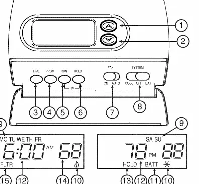
- Raises/Lowers temperature: Use the arrow buttons.
- TIME: Used to set the current time and day.
- PRGM: Used to enter programming mode.
- RUN: Used to return to normal operation.
- HOLD: Used to maintain a specific temperature indefinitely or for a set duration.
- FAN Switch: Set to ON (continuous blower) or AUTO (blower runs only with system).
- SYSTEM Switch: Set to COOL, OFF, or HEAT.
Programming
Setting Time and Day: Press the TIME button once to set the hour, then again for minutes, and again for the day of the week. Use the arrow buttons to adjust values.
Heating/Cooling Schedules: You can program four periods per day for weekdays, Saturday, and Sunday. Move the SYSTEM switch to HEAT or COOL. Press PRGM to enter programming mode. Use the arrow buttons to set the temperature and the TIME button to set the start time for each period. Repeat for all periods and days, then press RUN to finish.
Configuration Menu
To enter the configuration menu, press RUN, then press PRGM and RUN simultaneously. Use the HOLD button to advance through menu items and the arrow buttons to change settings:
- Temporary Hold Time: 0 to 8 hours in 15-minute increments.
- Heating Cycle Rate: Select FA (Fast) for gas/oil/electric or SL (Slow) for hydronic systems.
- Backlight: Turn ON or OFF.
- Energy Management Recovery: Turn ON or OFF.
- Filter Replacement: Set run time from 0 to 1950 hours.
- Compressor Lockout: Turn ON or OFF to protect the compressor.
- Temperature Adjustment: Adjust display +/- 4 degrees.
- F/C Readout: Select Fahrenheit or Centigrade.
Troubleshooting
If the thermostat malfunctions, try the reset procedure: press the up arrow, down arrow, and TIME button simultaneously. This resets the factory defaults. For specific issues like 'No Heat' or 'No Cool', check the system switch position, ensure the furnace power is ON, and verify that all wiring connections are secure.
Practical help
Common problems
No Heat/No Cool/No Fan
Check for a blown fuse or tripped circuit breaker. Ensure the furnace power switch is ON and the blower compartment door is properly installed.
Display is blank or keypad not responding
Replace batteries. If the issue persists, perform a reset by pressing the up arrow, down arrow, and TIME button simultaneously.
Thermostat does not follow program
Check that AM/PM designations are set correctly for both the clock and the program periods.
Furnace cycles too fast or too slow
Adjust the cycle rate in the configuration menu (Item 2). Use FA for fast or SL for slow.
Before use
- Disconnect electrical power at the main fuse box.
- Label all wires before disconnecting the old thermostat.
- Ensure your system is low voltage (do not use on line voltage).
- Remove the battery tag to engage the included AA batteries.
- Verify the system type (e.g., heat pump, electric, gas) to set the correct wiring and configuration.
Specs in practice
- Electrical Rating
- 8 to 30 VAC 50/60 Hz or D.C. (1.5 Amps maximum total load).
- Setpoint Temperature Range
- 45°F to 90°F (7°C to 32°C).
- Operating Ambient Temperature
- 32°F to 105°F.
Images and diagrams
- Figure 1: Shows the thermostat base, mounting holes, and the Electric/Gas switch location.
- Figures 2-7: Provide wiring schematics for various system types, including heat-only, cool-only, and heat pump configurations.
Model compatibility
- Compatible with: Standard heat/cool, electric heat, gas/oil, hydronic (hot water/steam), single-stage heat pump, and millivolt systems.
- Not compatible with: Multi-stage systems, systems exceeding 30 VAC/1.5 amps, or 3-wire zoned hydronic heating systems.

Manual page author
Michael Turner
Technical manual editor
Reviews PDF manuals for structure, safety notes, and practical product details so readers can find the right information quickly.