Industrial / Communication Modules
Service Manual for Secop 101N2050 Controller
A comprehensive service guide for the Secop 101N2050 controller. Includes instructions for clearing E1 and E6 errors, performing controller resets, wiring diagnostics, and troubleshooting common faults.
Table of contents
Manual images
Click an image to enlargeQuick Guide for Service and Diagnostics
This document provides practical, test-based procedures for the Secop 101N2050 controller, specifically for Iveco refrigeration units. It is intended for qualified personnel only. Warning: Incorrect wiring may cause damage to the controller, installation, or compressor. Always verify the production date, CODE, and program version before selecting a procedure.
Key Requirements:
- Minimum supply voltage: 25 V.
- Procedures must be performed by qualified personnel.
- Hard reset requires disconnecting the 2-pin power connector.
Controller Identification
The 101N2050 designation alone is not sufficient to identify the controller version. Before selecting a procedure, verify the production date, CODE, program, wiring configuration, and behavior of the specific unit using the label on the controller housing.
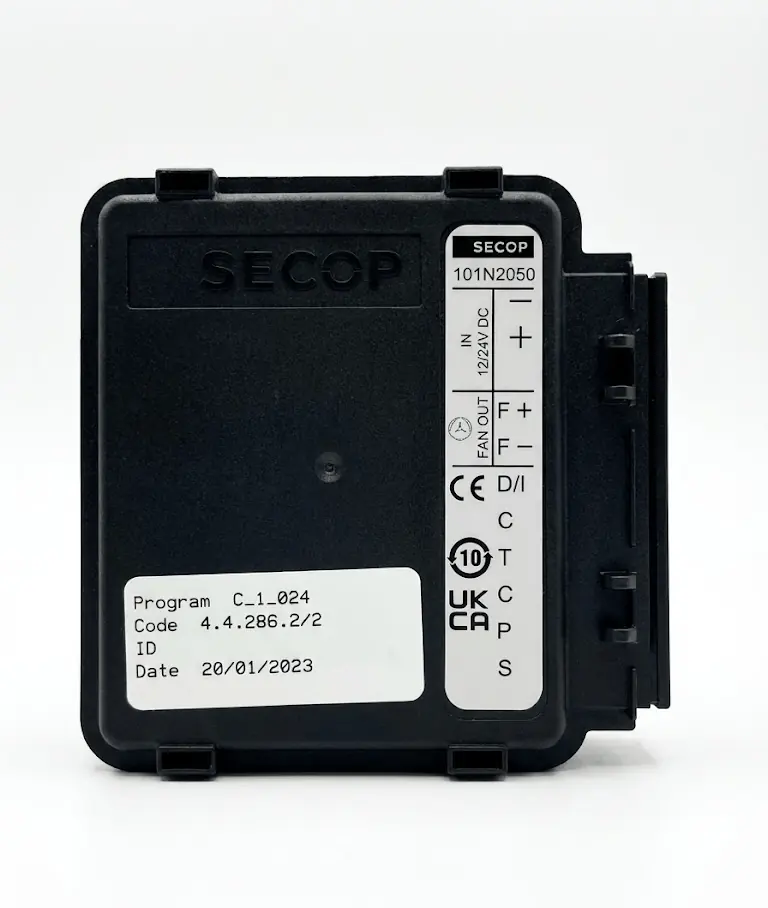
Wiring and Pinout
The controller features a 2-pin power connector and an 8-pin connector for diagnostics and fan control. Key pins include:
- 1 (-): Main negative supply (2-pin connector).
- 2 (+): Main positive supply (2-pin connector).
- 3 (F+): Fan output.
- 4 (F-): Fan output.
- 5 (D/I): Input / diagnostic communication line (used for reset).
- 9 (P): Programming pin (also used in reset procedures).
Test Conditions
Before testing, perform a pre-test inspection: check the condition of supply wires and connectors, ensure no burned contacts, and verify that connectors are properly seated. To perform a basic test:
- Disconnect supply.
- Make test connections.
- Reconnect supply.
- Wait approximately 10 seconds.
- Observe controller and panel response.
Reset Procedures
The following procedures are used to clear faults and reset the controller:
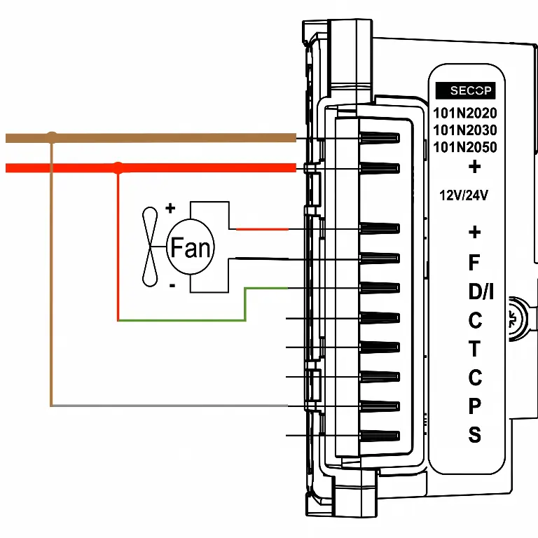
Reset E1 (Positive to D/I and P)
- Disconnect supply.
- Connect heavy positive (red) to D/I (green).
- Connect heavy positive (red) to P (white).
- Connect supply (min. 25 V).
- Wait 10 seconds.
- Check display; E1 errors should be cleared.
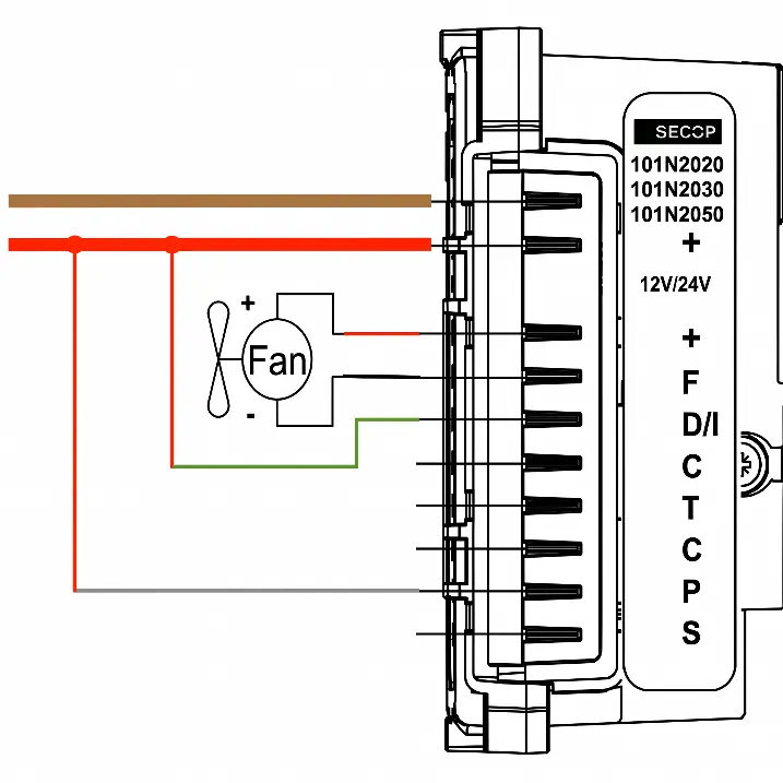
Reset E6 (Negative to P, Positive to D/I)
- Disconnect supply.
- Connect heavy negative (brown) to P (white).
- Connect heavy positive (red) to D/I (green).
- Connect supply (min. 25 V).
- Wait 10 seconds.
- Check controller and panel response.
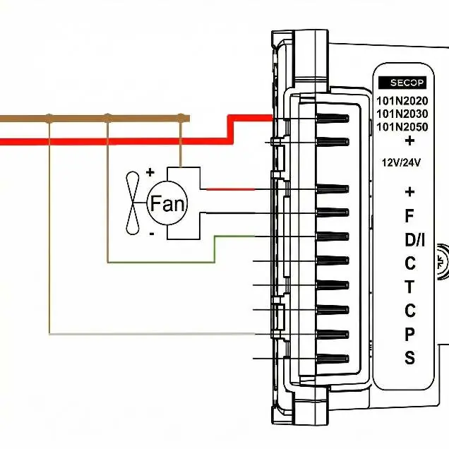
Hard Reset (Reversed Line Polarity)
Warning: Before proceeding, disconnect the 2-pin power connector from the controller. Applying positive voltage to the negative pin with the connector attached will damage the controller.
- Disconnect supply.
- Disconnect 2-pin connector from controller.
- Connect heavy positive (red) to controller negative pin.
- Connect heavy negative (brown) to F+ (thin red).
- Connect heavy negative (brown) to D/I (green).
- Connect heavy negative (brown) to P (white).
- Connect supply (min. 25 V).
- Wait 10 seconds.
- Observe controller response.
- Restore standard connections after test.
Frequently Asked Questions
How to clear E1 and E6 errors? Verify correct supply voltage and perform one of the confirmed reset variants (positive to D/I and P, or negative to P and positive to D/I).
How to unlock the controller after a fault? In some cases, the controller can be quickly unlocked by connecting the D/I and P wires to the positive and negative supply terminals.
Practical help
Common problems
Persistent E1 or E6 fault
Perform the specific reset procedure (E1 or E6) using the correct wiring configuration.
Compressor fails to start
Verify supply voltage is at least 25 V and check for loose or open connections.
Controller enters lockout
Perform a reset procedure to attempt to restore system operation.
Before use
- Verify production date, CODE, and program version.
- Ensure supply voltage is at least 25 V.
- Check for burned contacts on connectors.
- Ensure all connectors are properly seated.
- Verify condition of supply wires.
Images and diagrams
- Wiring diagrams illustrate the specific pin connections required for E1 reset, E6 reset, and Hard Reset procedures.
- The diagrams show the connection between the heavy positive/negative supply lines and the specific controller pins (D/I, P, F+).
Model compatibility
- Procedures apply to Secop 101N2020, 101N2030, and 101N2050 controllers.
- Hard reset is not universal for all 101N2050 units.
- Procedures are based on practical testing and are not official manufacturer documentation.

Manual page author
Michael Turner
Technical manual editor
Reviews PDF manuals for structure, safety notes, and practical product details so readers can find the right information quickly.