Industrial / Access Control
User Manual for Security Brands 14-REC300 Wireless Access Control Receiver
Quick guide for the Security Brands 14-REC300 Wireless Access Control Receiver. Learn how to set DIP switches, wire the unit to your gate operator, and troubleshoot connectivity issues.
Table of contents
Quick guide from the manual
The Security Brands 14-REC300 is a wireless access control receiver designed for gate and door operators. Important: Do not exceed 12 VAC/DC power input, as this will damage the unit. For optimal performance, ensure the antenna is not blocked by metal enclosures; if mounting inside a metal box, use the optional 14-ANT300 external antenna kit. Always ensure DIP switch positions on the receiver match those on your remote control.
Device overview
The receiver unit consists of the following components:
- DIP switches: Used for security coding and matching with remotes.
- RF status LED: Indicates signal activity.
- Power and relay terminals: Connection points for power and gate operator interface.
- Coaxial antenna connector: Connection point for the included antenna.
Setup and DIP switches
To configure the receiver:
- Remove the screws from the unit cover and carefully remove the cover to reveal the DIP switches. Caution: Be gentle with the coaxial connection when removing the cover; do not let the cover hang free.
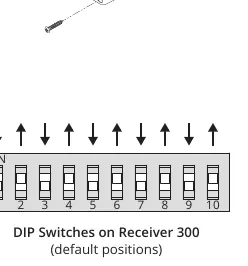
- Set the DIP switches to your desired positions. By default, these are matched to the Security Brands Remote 300 (14-R300).
- Note that some switches may be labeled differently (e.g., position 10 corresponds to 0, or 'OFF' may be labeled as 'OPEN').
Wiring and installation
Follow these steps to install the receiver:
- Wiring: Connect power and relay wires to the screw terminals on the receiver. Connect the other ends to your gate or door operator according to the operator's manual. Tighten all screws securely.
- Mounting: Mount the receiver unit near the gate or door operator control circuit board using Tek screws or zip ties via the mounting slots.
- Antenna: Securely connect the included antenna to the coaxial connector on the bottom of the unit. Slide the rubber sleeve over the connector for protection.
How to use
Ensure you are within range of the receiver. Press the button on your linked remote. The receiver will respond and trigger the gate or door operator. If the receiver does not respond, verify that it has power, the antenna is not blocked, and the DIP switch settings match the remote.
Support
For technical assistance, you can call (972) 474-6390 or email [email protected].
Manufacturer information
Security Brands, Inc.
Practical help
Common problems
Receiver does not respond to remote
Ensure the unit has power, the antenna is not blocked by metal, and the DIP switch positions on the receiver match the remote.
Unit damaged during installation
Ensure power input does not exceed 12 VAC/DC. Do not let the cover hang by the coaxial cable when opened.
Before use
- Verify power source is 12 VAC/DC.
- Ensure antenna is securely connected.
- Match DIP switch positions on receiver and remote.
- Check that the gate path is clear of obstructions.
- Ensure safety devices are installed on the gate operator.
Images and diagrams
- Wiring diagram illustrates connections between Receiver 300 terminals and Gate/Door Operator terminals.
- DIP switch diagram shows default switch positions.
Model compatibility
- Recommended for use with Security Brands Remote 300 (14-R300).
- If mounting inside a metal enclosure, use external antenna kit 14-ANT300.

Manual page author
Michael Turner
Technical manual editor
Reviews PDF manuals for structure, safety notes, and practical product details so readers can find the right information quickly.