Industrial / Access Control
Installation Guide for Security Brands 14-RTE433T Ridge RTE Unit
Quick installation and setup guide for the Security Brands 14-RTE433T Ridge RTE Unit. Includes wiring diagrams, pairing instructions, and troubleshooting steps for gate and door access control systems.
Table of contents
Manual images
Click an image to enlargeImportant Information
The Ridge RTE Unit (14-RTE433T) is an access control device designed for gate and door operation. Important: The transceiver is not weatherproof and must be mounted inside a weatherproof enclosure to prevent damage. Always ensure the gate path is clear before performing any testing or pairing procedures, as these actions trigger the relay.
Components
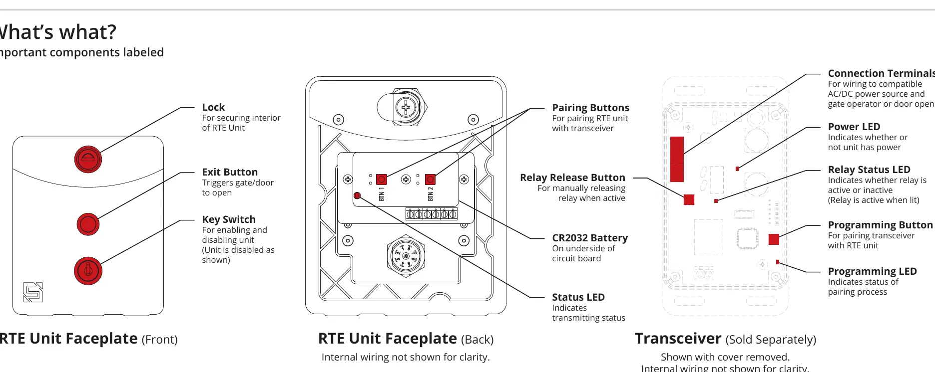
The package includes the RTE Unit (with battery), key switch keys, lock key, carriage bolts (4x), hex nuts (4x), hole plug, and a screwdriver. The system consists of the RTE Unit (faceplate with exit button, key switch, and lock) and a separate Transceiver.
Installation
1. Unlock and remove the faceplate of the RTE unit.
2. Use the included carriage bolts and hex nuts to attach the unit to the pedestal.
3. Attach the transceiver to an inside wall or surface within the gate operator using Tek screws, zip ties, or other secure means.
Wiring
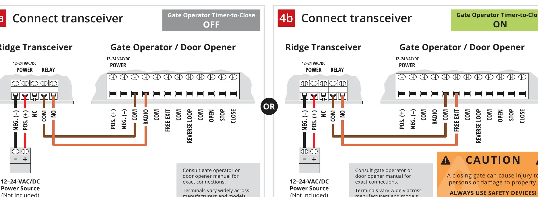
The transceiver connects to a 12-24 VAC/DC power source and the gate operator/door opener. Consult your gate operator manual for specific terminal connections, as they vary by manufacturer. The guide provides specific wiring diagrams for configurations with the Gate Operator Timer-to-Close feature set to OFF or ON.
Pairing
1. Remove the transceiver cover and hold the Programming Button on the circuit board for 5 seconds, then release. The LED will light and stay on.
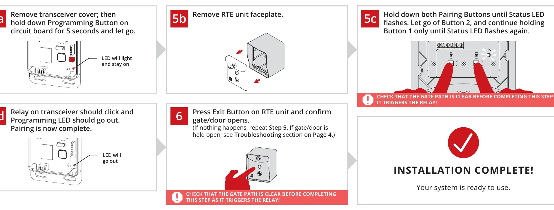
2. Remove the RTE unit faceplate.
3. Hold down both Pairing Buttons on the RTE unit until the Status LED flashes. Release Button 2, but continue holding Button 1 until the Status LED flashes again.
4. The relay on the transceiver should click, and the Programming LED should go out, indicating pairing is complete.
5. Press the Exit Button on the RTE unit to confirm the gate/door opens.
Operation
The RTE unit can be enabled or disabled at any time using the key switch located below the Exit Button. When the unit is disabled, the Exit Button is inactive.
Reset Procedure
To unpair all devices (keypads, RTEs, and remotes) from the transceiver:
- Ensure the transceiver has power and remove the cover.
- Press and hold the Programming Button until the Programming LED starts to flash (hold for approximately 30 seconds).
- Once the flashing stops, all devices are unpaired.
- Replace the transceiver cover and secure the screws.
Troubleshooting
If the gate/door is held open, ensure the gate is closed, then hold both Pairing Buttons on the RTE unit. When the Status LED flashes twice, continue holding both. When it flashes twice again, hold Button 1 only until the Status LED flashes multiple times. If the issue persists, press the Relay Release Button on the transceiver.
For limited range issues, disconnect power, check the position of the blue wire coil on the transceiver (it should be secured in the terminal block labeled ANTENNA), and adjust if necessary.
For further assistance, contact support at 972-474-6422 or email [email protected]. Support is available Monday-Friday, 8am-5pm Central.
Manufacturer information
Security Brands, Inc.
Practical help
Common problems
Gate/door is being held open
Perform the re-pairing procedure: Hold both Pairing Buttons on the RTE unit, wait for Status LED flashes, and follow the specific button-holding sequence described in the troubleshooting section.
RTE unit has limited range
Disconnect power. Check that the blue wire coil on the transceiver is secured in the terminal block labeled ANTENNA. If not, move it to the correct terminal block.
Gate/door opening/closing without input
Perform the Reset Procedure (Section B) to unpair all devices and reset the transceiver.
Before use
- Verify all components are present (RTE unit, keys, bolts, nuts).
- Ensure a 12-24 VAC/DC power source is available.
- Confirm the transceiver is mounted inside a weatherproof enclosure.
- Ensure the gate path is clear before testing.
- Check that the transceiver has power before pairing.
Images and diagrams
- The 'What's what' diagram identifies the Exit Button, Key Switch, Pairing Buttons, and LEDs.
- Wiring diagrams illustrate connections for both Timer-to-Close OFF and ON scenarios.
Model compatibility
- Transceiver is not weatherproof; must be mounted inside a weatherproof enclosure.
- Gate operator terminals vary widely; consult the operator's specific manual for exact connections.

Manual page author
David Miller
Documentation analyst
Organizes user manual content into clear summaries, with attention to model details, product context, and everyday usability.