Industrial / Access Control
User Guide for Security Brands Ridge RTE 14-RTE433T
Quick start guide for the Security Brands Ridge RTE 14-RTE433T. Includes installation steps, wiring diagrams for gate operators, pairing instructions, and troubleshooting.
Table of contents
Manual images
Click an image to enlargeQuick Guide
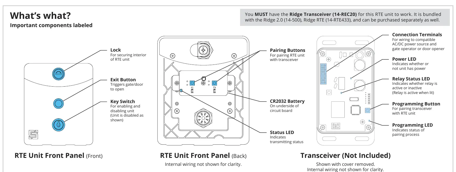
The Security Brands Ridge RTE 14-RTE433T is a wireless Request-to-Exit unit. Important: This unit requires the Ridge Transceiver (14-REC20) to function. It is bundled with the Ridge 2.0 (14-500) and Ridge RTE (14-RTE433), or can be purchased separately.
Components
The package includes the RTE unit (with battery), key switch keys, lock key, carriage bolts, hex nuts, and hole plugs. The RTE unit features a lock for security, an exit button to trigger the gate/door, and a key switch to enable/disable the unit.
Installation
Mounting: Unlock and remove the front panel of the RTE unit. Use the included carriage bolts and hex nuts to attach the unit to the pedestal. Attach the transceiver to the inside wall or another surface of the gate operator using Tek screws, zip ties, or the included adhesive mounting pad.
Caution: The transceiver is not weatherproof and must be mounted inside a weatherproof enclosure to prevent damage.
Wiring
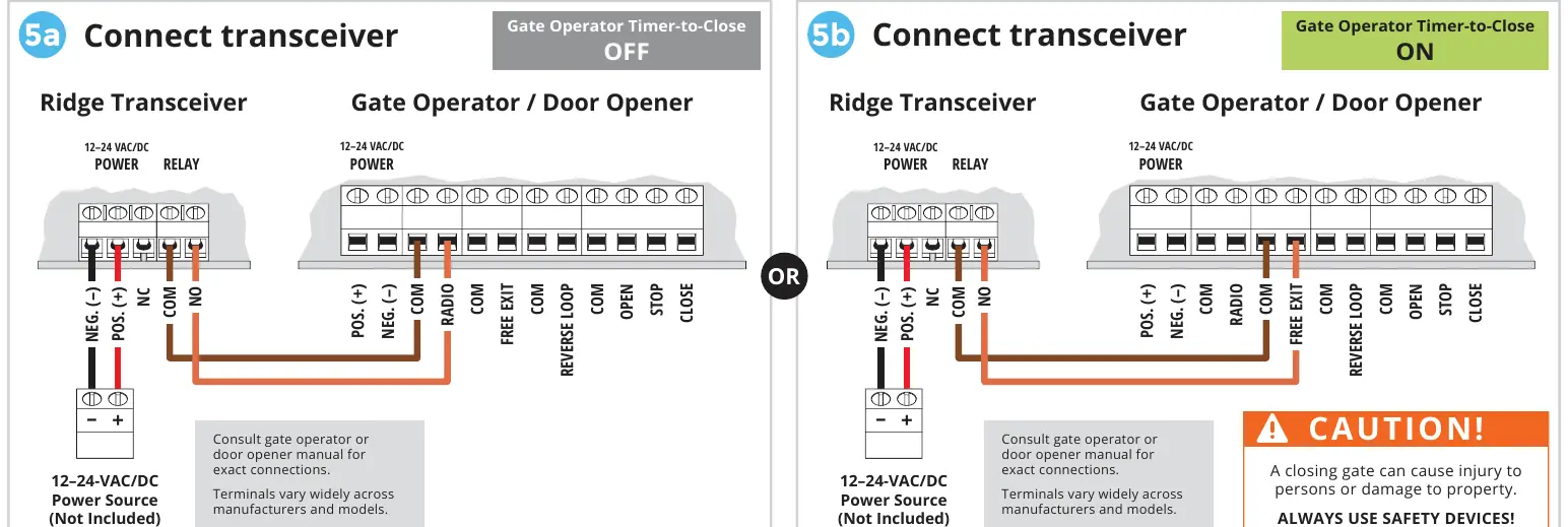
The transceiver connects to the gate operator or door opener. Wiring depends on whether the Gate Operator Timer-to-Close feature is OFF or ON. Consult your gate operator or door opener manual for exact terminal connections, as they vary widely across manufacturers.
Pairing Procedure
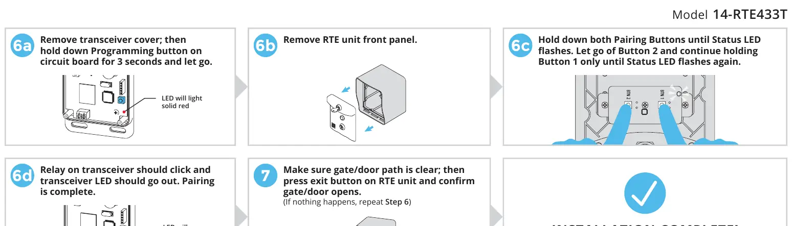
- Remove the transceiver cover.
- Hold down the Programming button on the transceiver circuit board for 3 seconds and release. The LED will light solid red.
- Remove the RTE unit front panel.
- Hold down both Pairing Buttons on the RTE unit until the Status LED flashes. Release Button 2 and continue holding Button 1 until the Status LED flashes again.
- The relay on the transceiver should click and the transceiver LED should go out, indicating pairing is complete.
- Test the system by pressing the exit button on the RTE unit to ensure the gate/door opens.
Operation and Reset
Enabling/Disabling: The RTE unit can be disabled and re-enabled at any time using the key switch keys located below the exit button.
Transceiver Reset: To unpair all devices, remove the transceiver cover, press and hold the Programming Button for about 30 seconds until the Programming LED stops flashing. Replace the cover and secure the screws.
Support
For technical assistance, call (972) 474-6390 or email [email protected]. Support is available Monday through Friday, 8am–5pm Central.
Manufacturer information
Security Brands, Inc.
Practical help
Common problems
Gate/door does not open when exit button is pressed
Ensure the unit is enabled via the key switch. If enabled, repeat the pairing procedure (Step 6) to ensure the RTE unit is correctly paired with the transceiver.
Transceiver LED does not light up
Check the power connection to the transceiver (12-24 VAC/DC) and ensure the power source is active.
Unit is disabled
Use the provided key switch keys to turn the key switch to the enabled position.
Before use
- Verify you have the Ridge Transceiver (14-REC20).
- Ensure a 12-24 VAC/DC power source is available.
- Check that the gate path is clear before testing.
- Have a screwdriver available for installation.
- Confirm the gate operator or door opener manual is available for wiring reference.
Images and diagrams
- Wiring diagrams illustrate connections for gate operators with Timer-to-Close set to OFF or ON.
- The 'What's what' diagram identifies the location of the battery, pairing buttons, and status LEDs.
Model compatibility
- Requires Ridge Transceiver (14-REC20) to operate.
- Compatible with gate operators and door openers; check specific manufacturer manuals for terminal compatibility.

Manual page author
Emily Carter
User documentation editor
Prepares concise manual descriptions and highlights the most useful setup, operation, and maintenance information for readers.