Industrial / Access Control
Installation Guide for Security Brands 14-RTE433 Wireless Exit Button Kit
A comprehensive installation and configuration guide for the Security Brands 14-RTE433 Wireless Exit Button Kit. Includes step-by-step wiring diagrams, pairing instructions, and troubleshooting procedures for gate operators.
Table of contents
Manual images
Click an image to enlargeQuick guide from the manual
This document provides installation and setup instructions for the 14-RTE433 Wireless Exit Button Kit. The system consists of an RTE Unit (Exit Button) and a Transceiver. Key requirements include a 12-24 VAC/DC power source and mounting the transceiver inside a weatherproof enclosure, as it is not weatherproof. Always ensure the gate path is clear before performing pairing or testing procedures.
Components Overview
The kit includes the following main components:
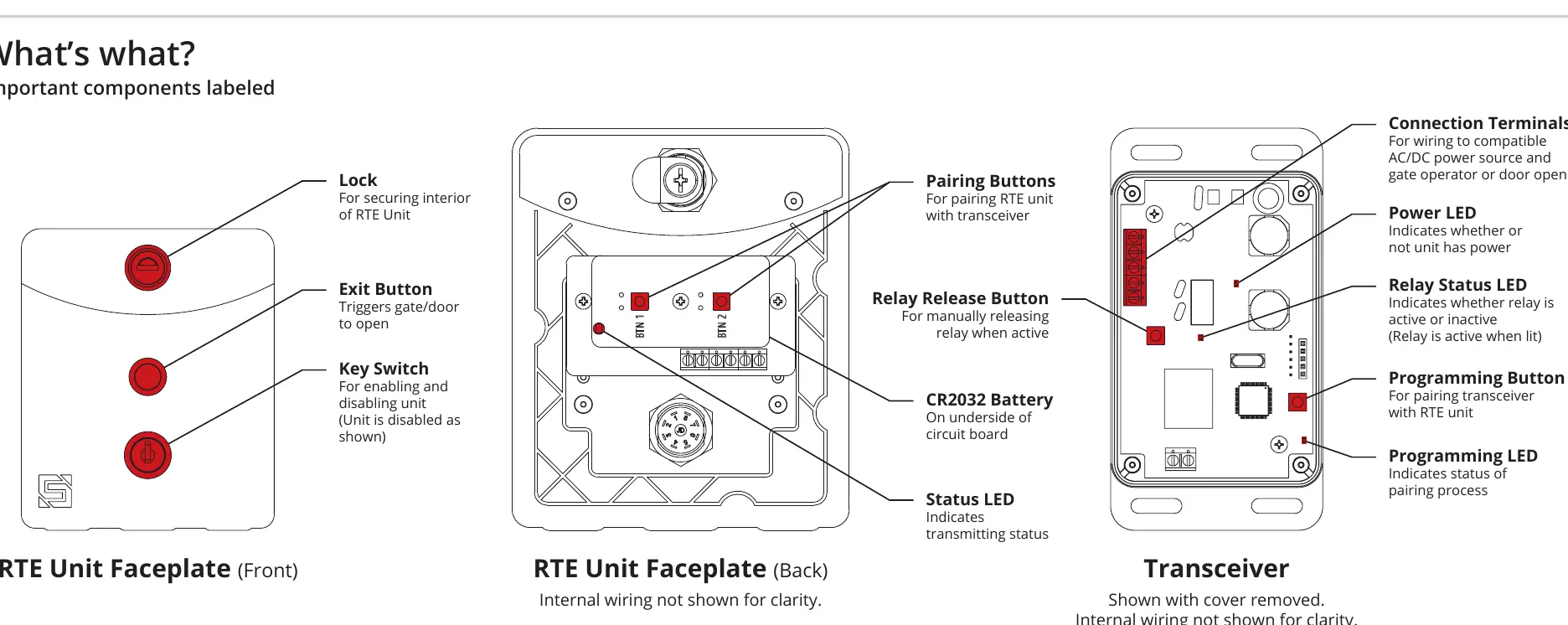
- RTE Unit: Features an Exit Button, Key Switch (for enabling/disabling), and a Lock for the faceplate.
- Transceiver: Contains connection terminals, a Programming Button, and status LEDs (Power, Relay Status, Programming).
- Hardware: Includes carriage bolts, hex nuts, and keys.
Installation and Mounting
Follow these steps to install the hardware:
- RTE Unit: Unlock and remove the faceplate. Use the included carriage bolts and hex nuts to attach the unit to the pedestal.
- Transceiver: Mount the transceiver inside the gate operator housing using Tek screws, zip ties, or similar fasteners. Ensure it is protected from the elements.
Wiring the Transceiver
The transceiver must be connected to a 12-24 VAC/DC power source and the gate operator. Terminals vary by manufacturer; consult your gate operator manual for specific connections.
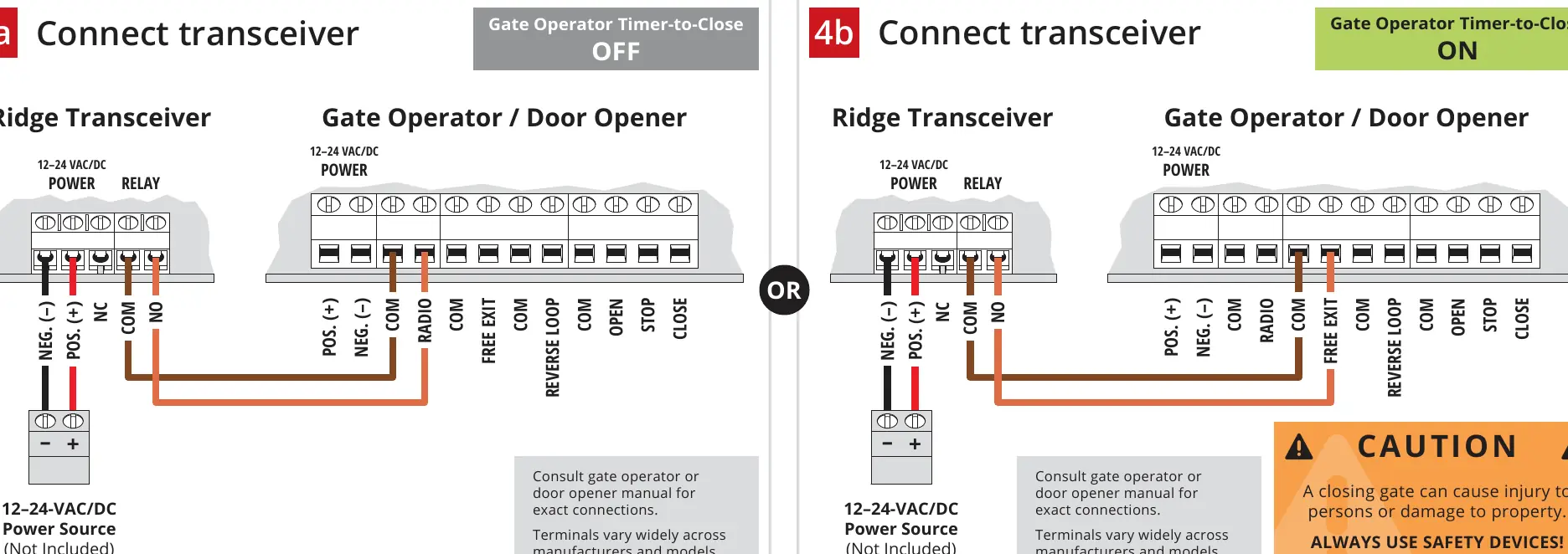
- Power: Connect the 12-24 VAC/DC power source to the Power terminals on the transceiver.
- Relay: Connect the NO (Normally Open) and COM (Common) terminals to the gate operator's input terminals.
Pairing the RTE Unit
To pair the RTE unit with the transceiver:
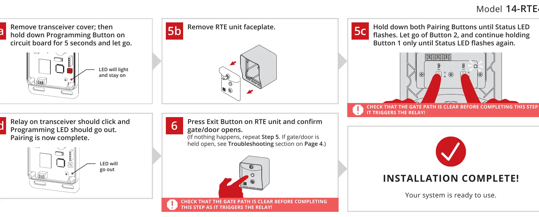
- Remove the transceiver cover and hold the Programming Button for 5 seconds.
- Remove the RTE unit faceplate.
- Hold down both Pairing Buttons on the RTE unit until the Status LED flashes.
- Release Button 2, but continue holding Button 1 until the Status LED flashes again.
- The transceiver relay should click, and the Programming LED should go out, indicating pairing is complete.
- Press the Exit Button to confirm the gate/door opens.
Operation and Key Switch
The RTE unit can be disabled or enabled at any time using the provided key switch located below the exit button. When the unit is disabled, the exit button will not trigger the gate.
Troubleshooting
If you encounter issues, refer to these solutions:
- Gate held open: Ensure the gate is closed. Follow the re-pairing procedure or press the Relay Release Button on the transceiver.
- Gate opening/closing without input: Perform the transceiver reset procedure.
- Limited range: Check the position of the blue wire coil (antenna) on the transceiver. It must be secured in the terminal block labeled ANTENNA.
Reset Procedure
To reset the transceiver and unpair all devices:
- Remove the transceiver cover.
- Press and hold the Programming Button until the Programming LED starts to flash (hold for approximately 30 seconds).
- Once the flashing stops, all devices are unpaired. Replace the cover.
Manufacturer information
Security Brands, Inc.
Practical help
Common problems
Gate/door is being held open
Ensure the gate is closed. Follow the re-pairing procedure or press the Relay Release Button on the transceiver to release the hold.
Gate/door opening/closing without input
Perform the full reset procedure on the transceiver to clear all paired devices.
RTE unit has limited range
Disconnect power and check that the blue wire coil (antenna) is properly secured in the terminal block labeled ANTENNA on the transceiver circuit board.
Before use
- Ensure the gate path is clear before testing.
- Verify you have a 12-24 VAC/DC power source.
- Ensure the transceiver is mounted inside a weatherproof enclosure.
- Consult the gate operator manual for specific terminal connections.
Specs in practice
- 12-24 VAC/DC
- Required voltage range for the transceiver power input.
- Relay Status LED
- Indicates if the relay is active (lit) or inactive.
Images and diagrams
- Wiring Diagram: Shows how to connect the transceiver power and relay terminals to the gate operator.
- Component Layout: Identifies the location of buttons, LEDs, and terminals on both the RTE unit and the transceiver.
Model compatibility
- The transceiver is not weatherproof and must be mounted inside a weatherproof enclosure.
- Gate operator terminals vary widely; always consult the specific operator manual for exact wiring.

Manual page author
Michael Turner
Technical manual editor
Reviews PDF manuals for structure, safety notes, and practical product details so readers can find the right information quickly.