Industrial / Access Control
Installation Guide for Security Brands Ascent X1 Cellular Telephone Entry System
Complete installation and wiring guide for the Security Brands Ascent X1 cellular telephone entry system. Includes mounting instructions, power requirements, relay and Wiegand device connections, and initial setup testing.
Table of contents
Manual images
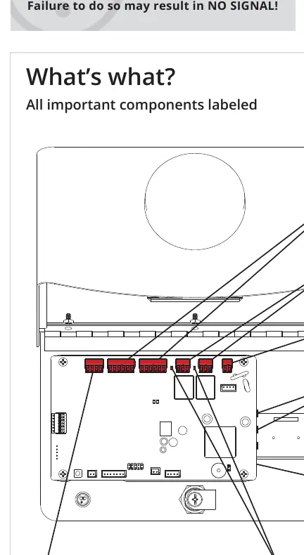
Click an image to enlargeQuick Start Guide
The Ascent X1 is a cellular accessory for gates and doors. Before beginning, ensure you have all components: the Ascent Unit, 12-V AC/DC Adapter (PS-12DC1), key, four carriage bolts, four hex nuts, and a screwdriver. Note that the unit will not function until the activation process is complete.
Safety Warnings
- Automatic Gates: Can cause serious injury or death. Always ensure the gate path is clear before operating.
- Safety Devices: Reversing or other safety devices should always be used.
- Emergency Access: An emergency egress or primary entry mechanism (transmitter, fire box, mechanical release) should always be installed.
- Power: Do not exceed 24 VAC/DC. Failure to use a compatible power source can damage the unit.
- Antenna: Leave the hockey puck antenna in place even if using an antenna extension.
Mounting Instructions
We recommend mounting the unit on a gooseneck pedestal using the included mounting hardware. Use all four carriage bolts when mounting the unit. If using alternate mounting, the 4G LTE Antenna Extension Kit (Model 16-ANTX-1) must be purchased and installed to prevent signal loss. Seal all openings created in the enclosure to prevent damage.
Wiring and Connections
Feed wires through the back of the unit. We recommend using 18-gauge stranded wire for all connections. Terminals can be unplugged to make wire connections easier.
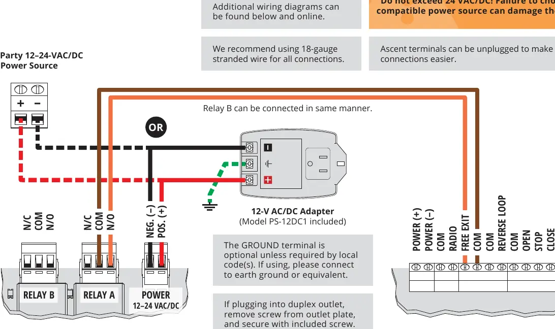
Power Connections
The unit accepts 12-24 VAC/DC. Verify your power source is compatible. If using a third-party power source, ensure positive is connected to positive and negative to negative. The GROUND terminal is optional unless required by local codes.
Relay and Wiegand Connections
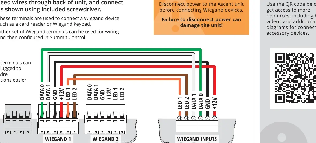
Relay terminals are used for connecting to gate operators or door openers. Wiegand terminals are used for connecting Wiegand devices such as card readers or keypads. Important: Disconnect power to the Ascent unit before connecting Wiegand devices to avoid damage.
Initial Setup and Testing
Once wiring is complete and the unit has power, perform the initial test: key in the temporary code 2012 on the keypad. If the gate opens, the installation is successful. Close and lock the unit faceplate. Adding and deleting codes is managed through Summit Control, not the keypad.
Manufacturer information
Security Brands, Inc.
Practical help
Common problems
Unit will not work
The activation process must be complete. See the included Activation Guide.
No signal
If not using a standard gooseneck pedestal, you must purchase and install the 4G LTE Antenna Extension Kit (Model 16-ANTX-1).
Unit damage
Do not exceed 24 VAC/DC power input. Ensure all enclosure openings are sealed.
Before use
- Verify power source is 12-24 VAC/DC (no more than 10% beyond this range).
- Ensure the gate path is clear before operating.
- Check that all four carriage bolts are installed for pedestal mounting.
- Ensure the activation process is complete.
- Disconnect power before connecting Wiegand devices.
Specs in practice
- Input Voltage
- 12-24 VAC/DC.
- Current Draw
- Less than 330 mA @ 12 VDC; less than 160 mA @ 24 VDC.
- Recommended Wire
- 18-gauge stranded wire for all connections.
Images and diagrams
- The wiring diagram illustrates connections for Relay A/B and Power terminals.
- The Wiegand diagram shows how to connect card readers or keypads to the Wiegand 1 or Wiegand 2 terminals.
Model compatibility
- Compatible with gate operators and door openers.
- Suitable for solar applications.

Manual page author
Emily Carter
User documentation editor
Prepares concise manual descriptions and highlights the most useful setup, operation, and maintenance information for readers.