Electronics / AV Switchers
User Manual for Stoltzen SHIFT USB 10G Switcher
Quick guide for the Stoltzen SHIFT USB 10G Switcher 2x1. Learn about installation, RS232 control, GPIO modes, and troubleshooting.
Table of contents
Manual images
Click an image to enlargeQuick guide from the manual
The Stoltzen SHIFT is a 2x1 USB 3.2 switcher designed to switch hosts and connect KVM devices. It supports 10Gbps bandwidth, auto-switching, and provides 2A of power for connected devices like cameras. The unit can be controlled via the front panel button, RS232, or GPIO.
Package contents
- 1 x SHIFT Switcher
- 2 x Mounting ears with 2 x screws
- 4 x Rubber feet
- 1 x 4-pin terminal block
- 1 x RS232 cable (3-pin to DB9)
- 1 x DC 12V 2A power adaptor
- 1 x User manual
Panel description
Front Panel:
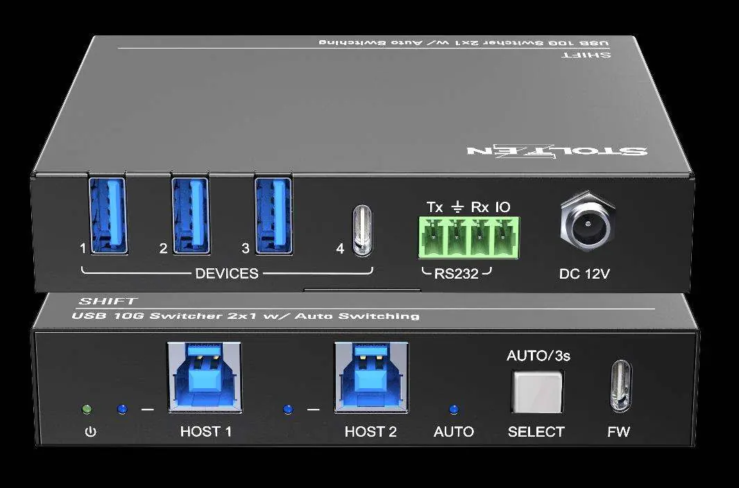
- LED Indicators: Power (green), Host (blue), Auto (blue).
- HOST Ports: 2x USB-B 3.2 Gen 2 for PC host connection.
- SELECT Button: Click to switch host; long press for 3 seconds to toggle automatic mode.
- Firmware Port: USB-C for upgrades.
Rear Panel:
- DEVICES: 3x USB-A and 1x USB-C 3.2 Gen 2 ports for KVM/camera devices.
- RS232 and GPIO: 4-pin terminal block for central control.
- DC IN: 12V 2A power input.
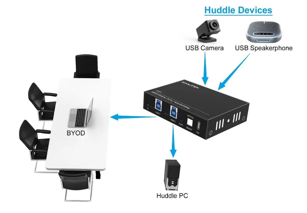
System connection
Ensure all devices are connected before powering on the unit. Install the device in a clean, well-ventilated environment. Connect your host computers to the HOST ports and your peripherals (camera, speakerphone, etc.) to the DEVICE ports.
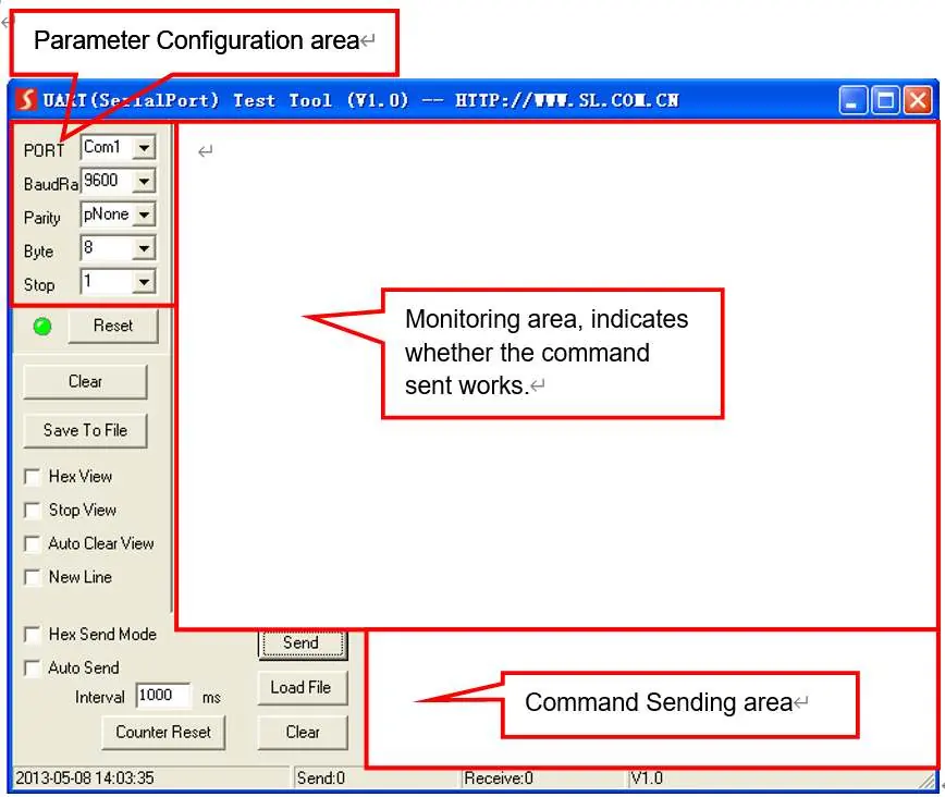
RS232 control
The switcher can be controlled via PC using RS232. Communication parameters: Baud rate 9600 (default), Data bit 8, Stop bit 1, Parity none. Use the command end symbol <CR><LF>.
Key Commands:
- >Help: Lists available commands.
- >GetStatus: Prints current status.
- >Reboot: Reboots the system.
- >FactoryReset: Resets to default settings.
- >SetAutoSwitch [param1]: Enables/disables auto-switching (On/Off).
- >SetIOMode [param1]: Sets IO control mode (00-02).
GPIO mode
The GPIO interface supports two modes:
- PULSE mode (default): Each transition from HIGH to LOW on the GPIN pin forces a host change.
- LEVEL mode: Uses level "0" (short to ground) to select Host 2 and level "1" (open) to select Host 1. Note: Buttons cannot be used to switch hosts in Level mode.
Troubleshooting
- No video/Color loss: Check if cables are connected correctly and are in good condition.
- Power indicator not working: Ensure the power cord is securely connected.
Warranty
The product includes a three-year limited warranty. Warranty exclusions include normal wear and tear, unauthorized modifications, use of non-compliant supplies, or missing proof of purchase.
Practical help
Common problems
Color loss or no video signal
Check if cables are connected correctly and are not damaged.
Power indicator does not light up
Ensure the power cord is securely connected to the DC IN port.
Before use
- Verify all package contents are present.
- Ensure the installation environment is clean with proper temperature and humidity.
- Connect all devices before powering on the unit.
- Ensure all power switches and cords are safe and insulated.
Specs in practice
- Power Output
- The four USB device ports share a total of 2A current.
- Operating Temperature
- -5°C to +55°C.
Images and diagrams
- Front panel features host ports, status LEDs, and the Select button for manual/auto switching.
- Rear panel contains device ports, RS232/GPIO terminal block, and power input.
Model compatibility
- Supports auto switching between two hosts.
- RS232 control requires specific baud rate settings (default 9600).

Manual page author
Emily Carter
User documentation editor
Prepares concise manual descriptions and highlights the most useful setup, operation, and maintenance information for readers.