Lighting / Ceiling Fans
User Manual for Summit X Series ESC
Quick guide for the Summit X Series ESC. Learn about wiring, programming parameters, throttle calibration, status tones, and telemetry setup for your electronic speed controller.
Table of contents
Manual images
Click an image to enlargeQuick Guide
The Summit X Series ESC is a high-performance electronic speed controller designed for RC models. This guide covers essential setup, wiring, and configuration. Always ensure the ESC is properly activated and calibrated before first use. The XHV series supports power input from 5S to 14S LiPo.
Wiring Diagram
The ESC requires connection to the receiver, telemetry adapter (optional), and the battery pack. Ensure the antispark plug is used correctly. The receiver connection handles throttle signal and power (4.8V-8.4V). Refer to the wiring diagram for the specific layout of the receiver, telemetry, and battery connections.
Programming Parameters
The ESC settings can be adjusted to optimize performance. Key parameters include:
- Rampup Power: Adjustable from 3% to 150%. Limits power during startup to facilitate low BEMF voltage detection.
- Motor Timing: Adjustable from 1° to 31° (or Auto). Higher timing improves margins against sync loss on difficult motors.
- PWM Frequency: Preconfigured range by the manufacturer.
- Demag Compensation: Protects against motor stalls caused by long winding demagnetization time. Higher values provide better protection.
- Motor Direction: Supports forward, reverse, and bidirectional modes (3D/Soft).
- Low Voltage Protection: Adjustable from 2.5V to 4.0V per cell. Limits power if battery voltage drops below the threshold.
- Temperature Protection: Limits motor power if internal temperature exceeds the programmed threshold.
Throttle Calibration
Throttle calibration is essential for the ESC to recognize the throttle range of your transmitter. Follow these steps:
- Power up the ESC.
- If throttle is above midstick for 3 seconds, the ESC measures and stores the max throttle.
- If throttle is below midstick for 3 seconds, the ESC measures and stores the min throttle.
- The ESC will emit specific beep sequences to confirm that the values have been stored.
Status Tones and Failures
The ESC communicates status via beep sequences:
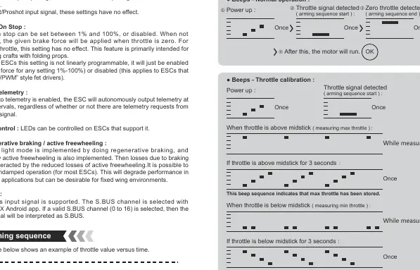
- Normal Operation: Upon power-up, the ESC detects the throttle signal. A low tone indicates input detection, and a high tone indicates the end of the arming sequence.
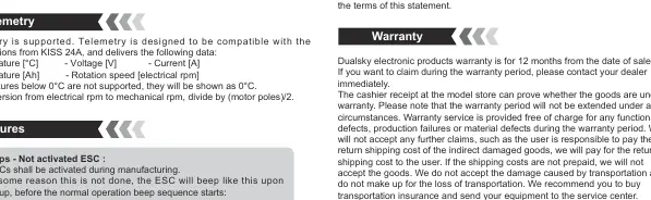
- Activation Failures: If the ESC was not activated during manufacturing, it will emit a specific error beep sequence upon power-up.
- Telemetry: The ESC supports telemetry compatible with KISS 24A specifications, providing data such as temperature, voltage, current, and rotation speed.
Warranty
Dualsky electronic products carry a 12-month warranty from the date of sale. Warranty covers functional defects, production failures, or material defects. It does not cover damage caused by water, reverse polarity, overload, or improper transportation. Proof of purchase (cashier receipt) is required for claims.
Practical help
Common problems
Motor stalls or stutters on quick throttle increase
Increase the Demag Compensation setting to improve protection against winding demagnetization.
Sync loss during operation
Increase the Motor Timing parameter to improve margins against sync loss.
ESC beeps continuously upon power-up
Check if the ESC is activated. If activation failed, the ESC will not operate normally and may only accept 1-2ms PWM input.
Before use
- Verify battery voltage is within the supported range (5S-14S Lipo for XHV).
- Ensure the receiver and telemetry connections are secure according to the wiring diagram.
- Perform throttle calibration before the first flight.
- Ensure the ESC has adequate ventilation.
- Check that the motor poles are correctly configured for telemetry RPM conversion.
Specs in practice
- Rampup Power
- Maximum power allowed during startup and low RPMs to help detect BEMF voltages.
- Motor Timing
- Adjusts the timing of the commutation cycle; higher values help with sync stability on less efficient motors.
- Demag Compensation
- Feature to prevent motor stalls after commutation; higher values offer better protection but may slightly reduce efficiency.
Images and diagrams
- Wiring Diagram: Illustrates the connection points for the receiver, telemetry adapter, battery, and antispark plug.
- Arming Sequence: Shows the timing of beeps from power-on to the ready-to-run state.
- Throttle Calibration: Displays the beep sequences for storing minimum and maximum throttle positions.
Model compatibility
- Telemetry is compatible with KISS 24A specifications.
- XHV series supports 5S to 14S LiPo batteries.
- S.BUS input signal is supported and selectable via the SUMMIT X Android app.

Manual page author
Emily Carter
User documentation editor
Prepares concise manual descriptions and highlights the most useful setup, operation, and maintenance information for readers.