Lighting / Controllers & Dimmers
User Manual for Sunricher 12W DALI DT8 LED Driver
Quick guide for the Sunricher 12W DALI DT8 LED Driver. Includes wiring diagrams, DIP switch current settings, installation safety, and technical specifications.
Table of contents
Quick Guide
The Sunricher 12W DALI DT8 LED Driver is a constant current power supply designed for Tunable White LED lighting. It features a 2-channel output with a selectable current range from 100mA to 700mA via DIP switches. The device supports DALI-2 and Push dimming interfaces and is compatible with universal DALI masters that support DT8 commands.
Safety and Warnings
- Do not install the device while power is applied.
- Do not expose the device to moisture.
- Ensure the installation complies with local electrical codes.
- This is a Class II power supply with a fully isolated plastic case.
Installation and Wiring
The driver requires connection to an AC power source (200-240V), a DALI bus, and the LED output channels.
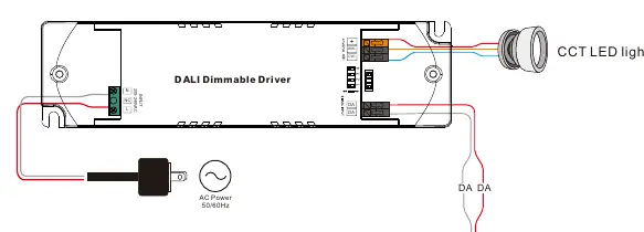
- AC Input: Connect to the L and N terminals.
- DALI Bus: Connect to the DA and DA terminals.
- LED Output: Connect the LED fixture to the WW (Warm White) and CW (Cool White) terminals.
Refer to the wiring diagram for the correct terminal layout. Ensure all connections are secure before applying power.
Operation and Settings
The output current is configured using the DIP switches located on the device. Match the switch positions (1, 2, 3, 4) to the desired current output as specified in the product data table (e.g., 100mA to 700mA). The DALI address is assigned automatically by the DALI Master controller.
Technical Specifications
- Input Voltage: 200-240V AC, 50/60Hz
- Rated Power: Max. 12W
- Output Current: 100-700mA (selectable)
- Dimming Interface: DALI Device Type 8
- Dimming Range: 0.1% - 100%
- Protection: Short circuit, over current, and over temperature protection with automatic recovery.
- Dimensions: 135 x 35 x 20 mm
Practical help
Common problems
Device not dimming
Ensure the DALI master controller supports DT8 commands and is correctly addressed.
LED flickering
Verify that the DIP switch settings match the current requirements of the connected LED fixture.
No output
Check AC power input and ensure all wiring connections are secure and correctly polarized.
Before use
- Ensure power is disconnected before installation.
- Verify the LED fixture voltage and current requirements.
- Set the output current using the DIP switches according to the LED specifications.
- Ensure the DALI bus polarity is correct.
- Confirm the installation environment is dry (IP20 rating).
Images and diagrams
- Wiring Diagram: Illustrates the connection points for AC power, DALI bus, and CCT LED lights.
- DIP Switch Table: Provides the switch configurations for selecting output currents from 100mA to 700mA.
Model compatibility
- Compatible with universal DALI masters that support DT8 commands.
- Designed for indoor LED lighting applications.

Manual page author
David Miller
Documentation analyst
Organizes user manual content into clear summaries, with attention to model details, product context, and everyday usability.