Toys / RC Models & Drones
User Manual for E-flite Super Timber 1.7m RC Airplane
Comprehensive user manual for the E-flite Super Timber 1.7m RC airplane. This guide includes detailed instructions for assembly, transmitter setup (DX, iX, NX series), SAFE Select configuration, battery and ESC management, center of...
Table of contents
Manual images
Click an image to enlargeQuick Guide from the Manual
The E-flite Super Timber 1.7m is a sophisticated RC model requiring basic mechanical knowledge. Before your first flight, ensure the model is properly assembled, the transmitter is programmed according to the specific series (DX, iX, or NX), and the Center of Gravity (CG) is balanced. Always perform a range check and verify control surface directions before takeoff.
Safety and Warnings
- Always maintain a safe distance from the model during operation.
- Do not operate near people, vehicles, or traffic.
- Keep small parts and electrical components away from children.
- Ensure the transmitter is on before connecting the flight battery.
- Remove the battery after every flight.
- Do not touch moving parts while the battery is connected.
Assembly
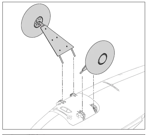
Landing Gear
Work with the fuselage inverted, using the packaging foam as a cradle. Insert the landing gear struts into the support bracket on the bottom of the fuselage. Secure each side with two M2 x 12 mm screws and M2 locknuts. Connect the landing gear springs to the axles and secure the spring retainer to the fuselage using two M3 x 12 mm self-tapping screws and M3 washers.
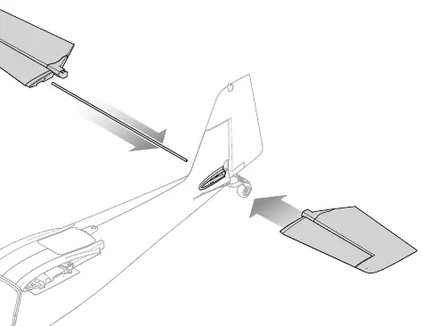
Tail Assembly
Slide the horizontal stabilizer tube (450 x 5 mm) into the rear fuselage hole. Install the left and right stabilizer halves until they click into place. Connect the elevator pushrod to the ball link on the elevator control horn.
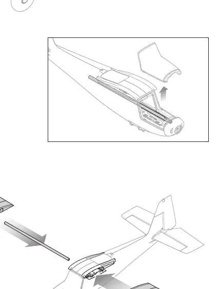
Wing Installation
Insert the wing joiner (560mm x 15mm) into the fuselage. Slide the wings onto the joiner and lock them into position using the locking mechanism on the bottom of the wings.
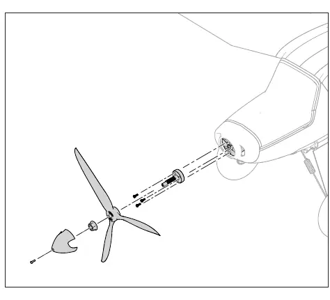
Propeller Installation
Install the propeller adapter onto the motor using three M3 x 8 mm screws. Mount the propeller and nut onto the shaft, tightening with a 15 mm wrench. Secure the spinner with an M3 x 10 mm screw, washer, and lock washer.
Transmitter Setup
The manual provides specific programming steps for Spektrum DX, iX, and NX series transmitters. Key settings include:
- Dual Rates & Expo: Aileron and Elevator settings (High: 100%, Expo 10%; Low: 70%, Expo 5%).
- Flap System: Configure switch positions for partial and full flaps.
- Throttle Cut: Set to Switch H, Position -100%.
Battery and ESC
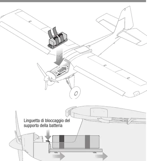
Recommended battery: 3200mAh 6S 22.2V Smart G2 LiPo 30C with IC5 connector. Ensure the battery is secured in the battery tray. The ESC is pre-programmed for Smart telemetry. If the motor pulses or loses power, the Low Voltage Cutoff (LVC) may have activated; land immediately and recharge the battery.
Binding and SAFE Select
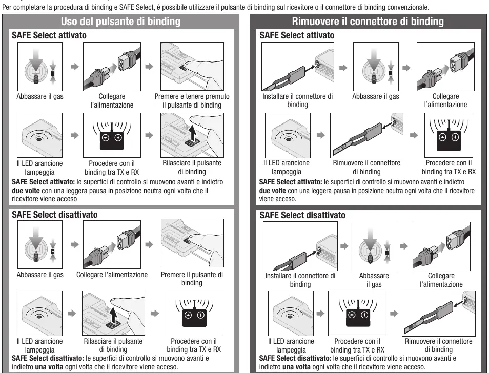
SAFE Select allows for flight envelope protection. It is enabled or disabled during the binding process. To bind, ensure the transmitter is set up correctly, then use the bind button on the receiver or the bind plug. Follow the specific sequence for either enabling or disabling SAFE Select as detailed in the manual.
Center of Gravity (CG)
The CG is measured from the wing leading edge. For general flight, set the CG at 105 mm. For aerobatics, set it at 110 mm. Always verify the CG before flight to ensure stability.
Troubleshooting
If the aircraft does not respond to throttle, ensure the throttle stick and trim are at the lowest position. If the aircraft experiences oscillations, reduce flight speed, check propeller balance, and ensure the receiver is securely mounted. If binding fails, increase the distance between the transmitter and receiver, and ensure no large metal objects are nearby.
Practical help
Common problems
Motor does not respond to throttle
Ensure throttle stick and trim are at the lowest position. Check if the motor is connected to the receiver.
Flight oscillations
Reduce flight speed, balance the propeller, and ensure the receiver is securely mounted.
Binding failure
Increase distance between transmitter and receiver, move away from metal objects/WiFi sources, and ensure the bind plug is inserted correctly.
Motor pulses or loses power
LVC (Low Voltage Cutoff) has activated. Land immediately and recharge the battery.
Before use
- Charge flight battery fully.
- Verify Center of Gravity (CG) is between 95-110mm.
- Check all control surfaces for correct movement and centering.
- Perform a range check.
- Ensure propeller is balanced and securely attached.
- Verify transmitter is programmed with correct dual rates and expo.
Images and diagrams
- Landing gear assembly: Shows strut insertion and spring attachment.
- Tail assembly: Illustrates horizontal stabilizer installation.
- Wing assembly: Shows joiner insertion and locking mechanism.
- Propeller installation: Details adapter, prop, and spinner mounting.
- Float installation: Shows strut and water rudder linkage.
Model compatibility
- Requires Spektrum DSMX compatible transmitter.
- Recommended battery: 3S-6S LiPo with IC5 connector.
- Compatible with Spektrum Smart telemetry.

Manual page author
Emily Carter
User documentation editor
Prepares concise manual descriptions and highlights the most useful setup, operation, and maintenance information for readers.