Toys / RC Models & Drones
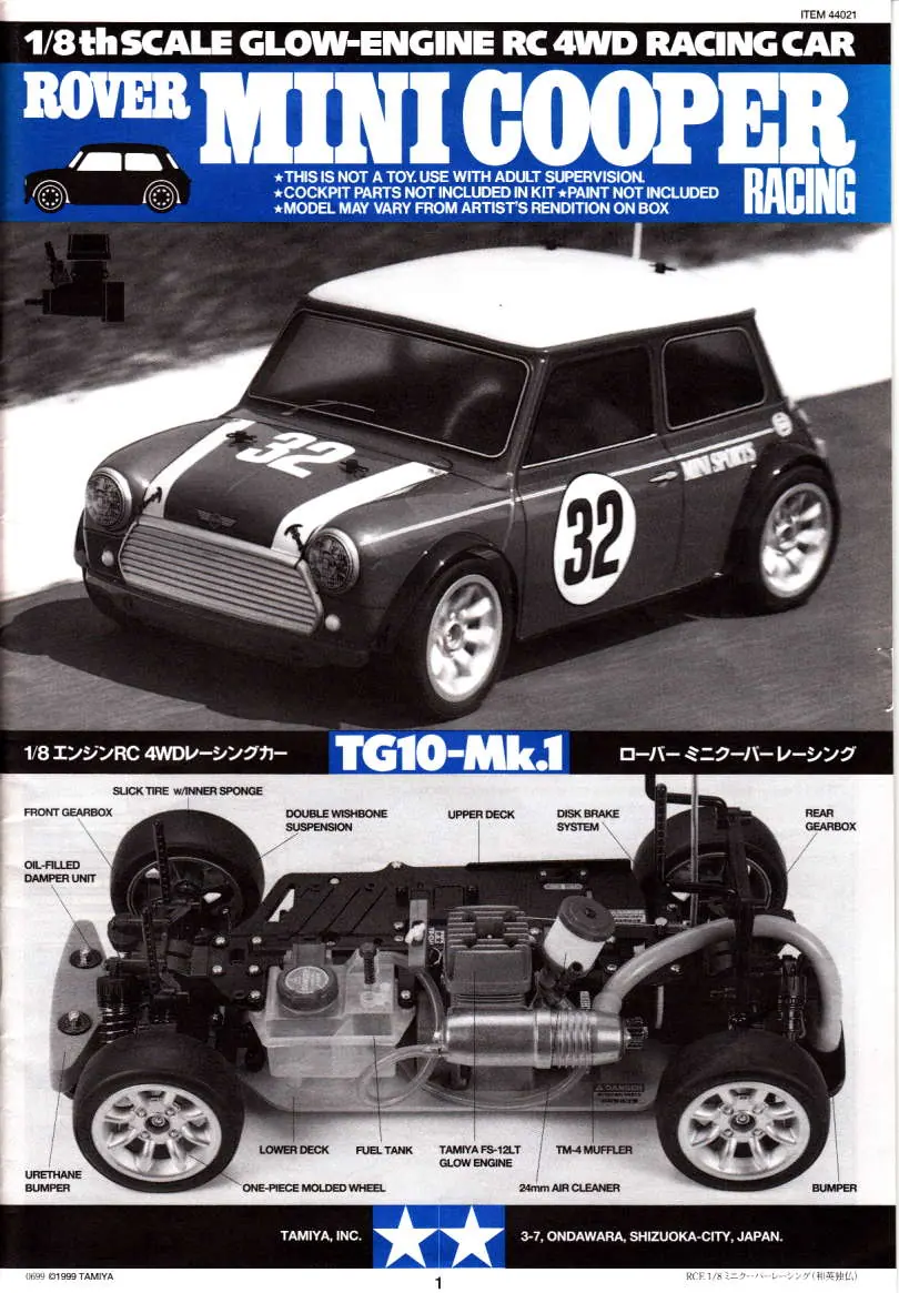
Tamiya Rover Mini Cooper Racing TG10-Mk.1 User Manual
Comprehensive user guide for the Tamiya Rover Mini Cooper Racing (TG10-Mk.1) 1/8 scale RC car. Includes assembly instructions, engine starting procedures, tuning tips, and troubleshooting.
Table of contents
Manual images
Click an image to enlargeQuick Guide from the Manual
This manual provides detailed assembly and operation instructions for the Tamiya Rover Mini Cooper Racing (TG10-Mk.1) 1/8 scale RC car. Before starting, ensure you have all necessary tools, including screwdrivers, pliers, and modeling knives. Adult supervision is required for assembly and operation. Always handle fuel and engine components with care, as they can become extremely hot during operation.
Assembly Instructions
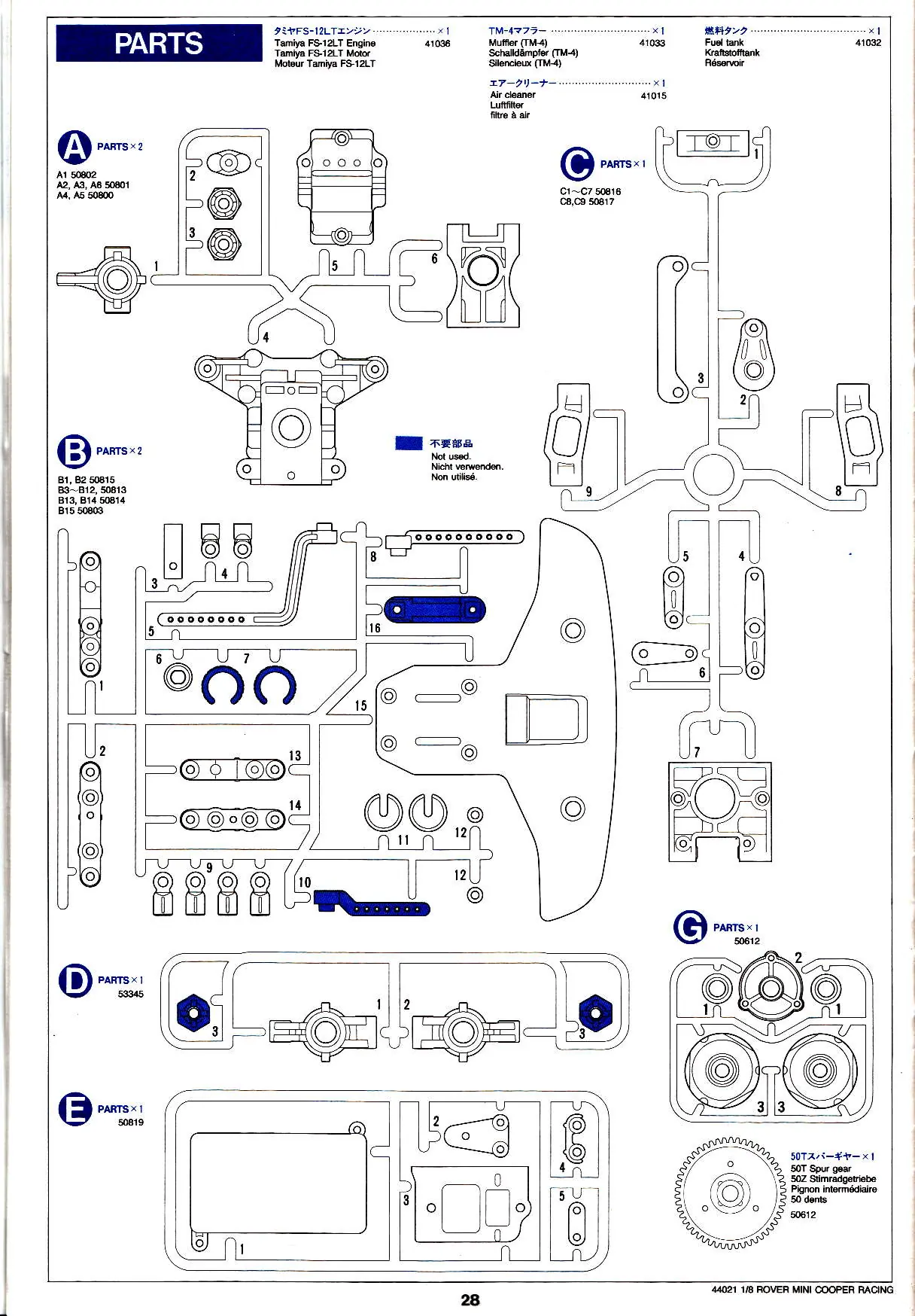
The assembly process is divided into several stages, utilizing specific parts bags (A through E). Follow the steps in numerical order:

- Gearbox and Rear Arms (Steps 1-11): Assemble the differential gear, gearbox, and rear suspension arms. Ensure all bearings are installed correctly.
- Front Arms and Steering (Steps 12-18): Assemble the front suspension arms, front axles, and steering linkage.
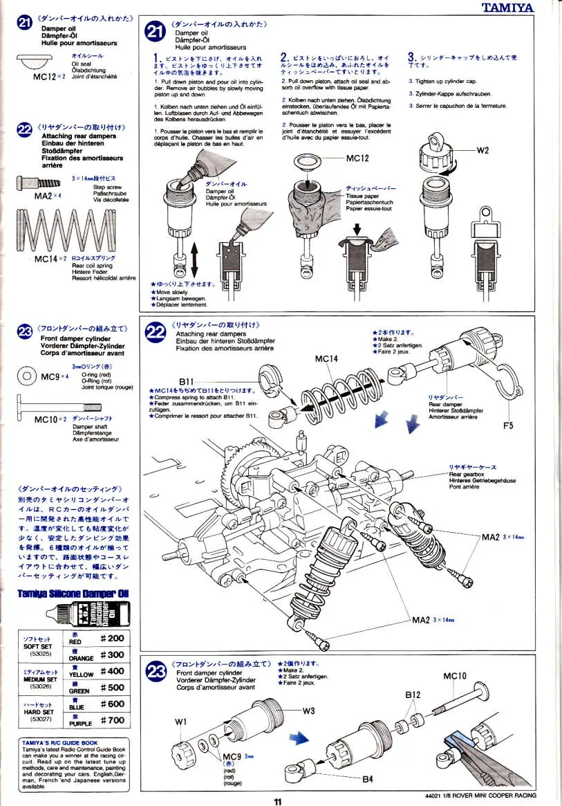
- Dampers (Steps 20-25): Assemble the oil-filled dampers. Fill with the appropriate damper oil to adjust suspension performance.
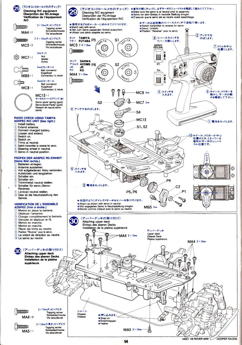
- Radio and Servos (Steps 26-27): Install the steering and throttle servos. Ensure the radio equipment is checked for neutral positioning before final installation.
- Fuel System (Step 28): Install the fuel tank and connect the fuel lines.
- Final Assembly (Steps 29-45): Complete the chassis, install the body mounts, trim the body shell, and apply stickers.
Engine Operation
The model uses a glow engine. Follow these procedures for safe operation:
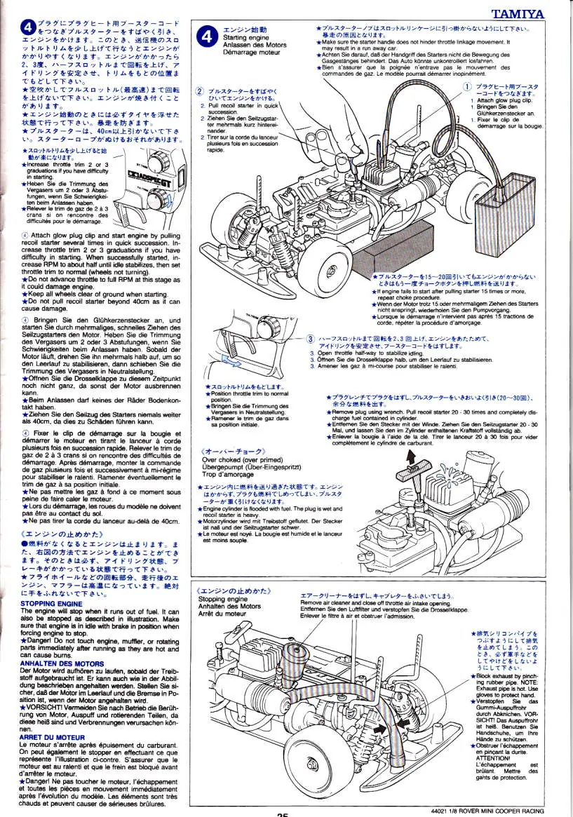
- Starting: Ensure the transmitter and receiver are on and the throttle is in neutral. Fill the tank with glow fuel. Prime the engine by pressing the choke button until fuel reaches the carburetor. Use a glow plug starter to ignite the engine.
- Tuning: Adjust the needle valve to fine-tune engine performance. If the engine stalls, check the fuel lines and needle valve settings.
- Stopping: The engine will stop when it runs out of fuel. You can also stop it by blocking the air intake or pinching the fuel line (use caution as the engine will be hot).
Maintenance and Troubleshooting
Regular maintenance is essential for performance:
- Cleaning: Keep the air filter, muffler, and engine clean.
- Storage: Do not leave fuel in the tank for extended periods.
- Troubleshooting: If the engine does not start, check for empty fuel tank, dead glow plug, or clogged fuel lines. If control is poor, check transmitter/receiver batteries and antenna extension.
Practical help
Common problems
Engine does not start
Check if the fuel tank is empty, the throttle valve is primed, the glow plug is functional, or if the engine is flooded (over-choked).
Engine stalls
Check for clogged fuel filter, muffler, or air cleaner. Ensure the pressure and fuel pipes are installed correctly. Adjust the needle valve.
Bad control
Replace weak batteries in the transmitter and receiver. Ensure antennas are fully extended. Adjust servo linkage.
Before use
- Check all screws and nuts are securely tightened.
- Ensure transmitter and receiver batteries are fresh.
- Verify steering servo is in the neutral position.
- Ensure fuel tank is filled with appropriate glow fuel.
- Check that the air filter is clean and properly installed.
- Ensure all antennas are fully extended.
Specs in practice
- Drive System
- 4WD (Four-Wheel Drive).
Images and diagrams
- Assembly diagrams use part codes (e.g., MA1, MA2) to identify specific screws and components.
- Arrows indicate the direction of assembly or movement.
- Star symbols indicate specific notes or warnings for that step.
Model compatibility
- Requires Tamiya ADSPEC GT-II or equivalent 2-channel R/C system.
- Uses Tamiya FS-12LT engine.
- Requires specific Tamiya polycarbonate paints for the body shell.

Manual page author
Emily Carter
User documentation editor
Prepares concise manual descriptions and highlights the most useful setup, operation, and maintenance information for readers.