Electronics / Networking
User Manual for TRENDnet TI-F711SFP Industrial 10G SFP+ Media Converter
Quick guide for the TRENDnet TI-F711SFP Industrial 10G SFP+ Media Converter. Learn about installation, DIP switch settings, power requirements, and technical specifications.
Table of contents
Manual images
Click an image to enlargeQuick guide from the manual
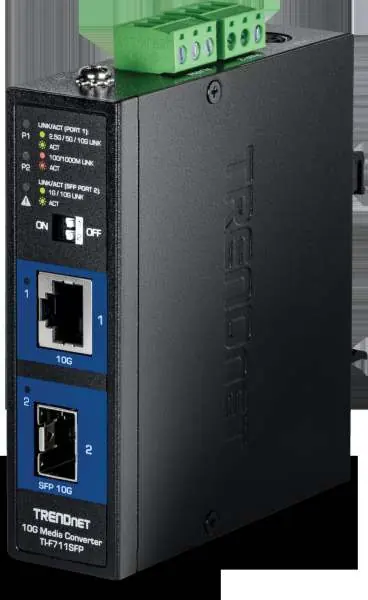
The TRENDnet TI-F711SFP is an industrial-grade 10G SFP+ to 10G Ethernet media converter designed for harsh environments. It features an IP50-rated metal housing, redundant power inputs, and an alarm relay. This guide provides essential information for installation, configuration, and operation.
Device Overview
The device includes the following key interfaces:
- 10G Ethernet Port: Supports 100Mbps/1G/2.5G/10G speeds.
- 10G SFP+ Port: Supports 1G/10G fiber modules (Multi or Single Mode).
- DIP Switches: Located on the front panel for configuring advanced features.
- LED Indicators: Provide status for Link/Activity on both ports.
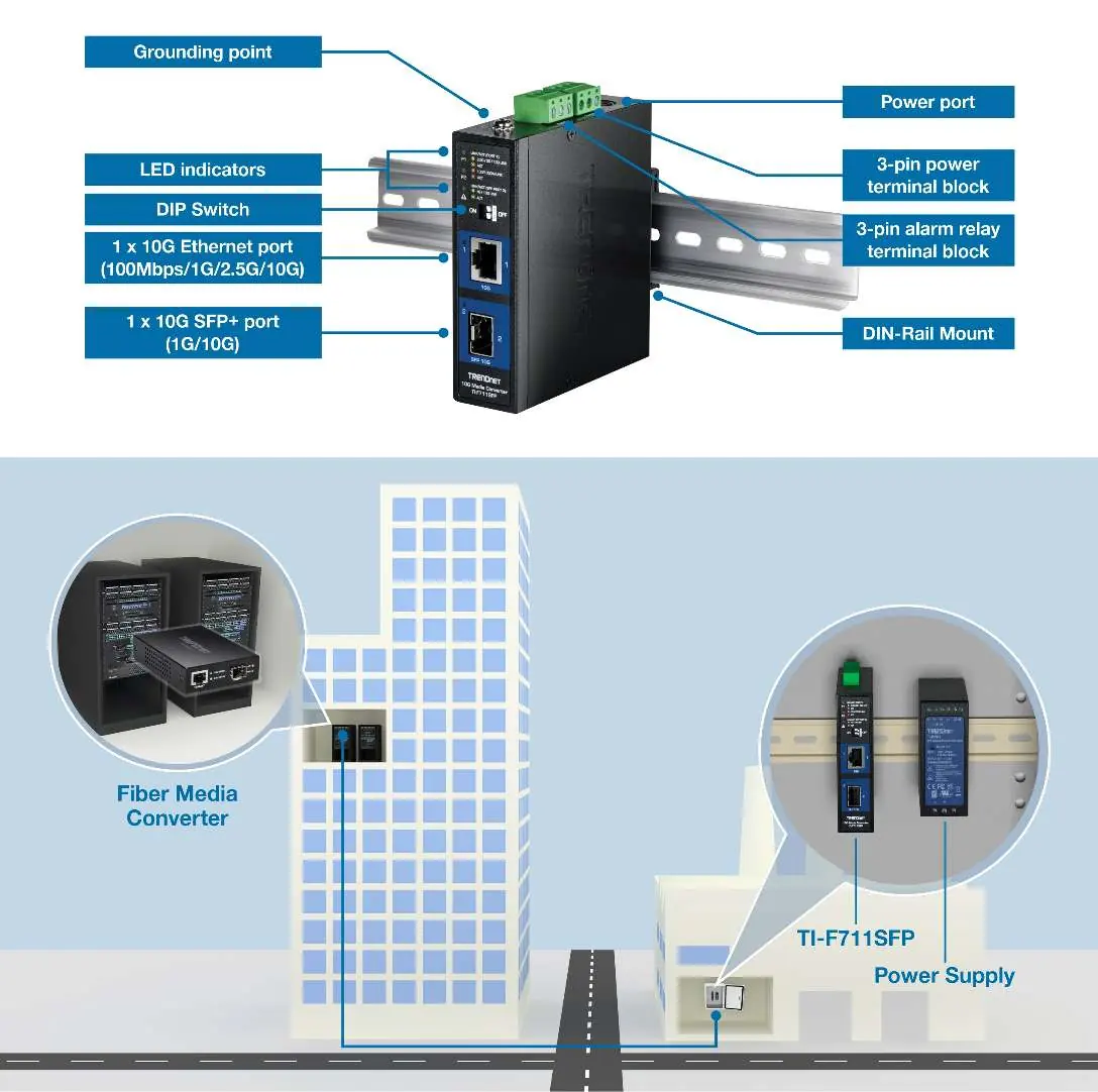
- Terminal Blocks: Located on the top for power input and alarm relay connections.
DIP Switch Settings
Configure the device behavior using the front panel DIP switches:
- Switch 1 (LFPT): Link Fault Pass Through. When enabled (default ON), it helps identify link faults to remote LFPT-enabled devices.
- Switch 2 (EEE): Energy Efficient Ethernet (IEEE 802.3az). Default is OFF.
Installation
The device is designed for industrial environments and supports the following mounting options:
- DIN-Rail Mount: Use the included hardware to attach the converter to a standard DIN-Rail.
- Wall Mount: Use the included wall mount hardware for surface installation.
- Grounding: Always connect the grounding point to protect the equipment from external electrical surges.
Power and Wiring
The device supports redundant power inputs to ensure continuous operation:
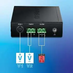
- Input Voltage: 9 – 60V DC.
- Redundancy: Dual power inputs (V1 and V2) allow for failover if one power source fails.
- Alarm Relay: Triggers in the event of a power failure.
- Terminal Block Specs: Supports wire range 12-25 AWG (solid or stranded). Strip length should be 7-8mm. Torque: 3.5 lb.-In / 0.5Nm.
Note: Power supplies (models TI-M6024 or 48VDC3000) are sold separately.
Technical Specifications
- Operating Temperature: -40° – 75°C (-40° – 167°F).
- Protection: IP50-rated metal case, 6kV RJ45 Ethernet surge protection, 6kV ESD protection.
- Compliance: Shock (IEC 60068-2-27), Freefall (IEC 60068-2-31), Vibration (IEC 60068-2-6).
- Dimensions: 120 x 98 x 30mm.
- Weight: 334g.
Practical help
Common problems
Power failure alarm triggered
Check both redundant power inputs (V1 and V2) to ensure they are connected and providing 9-60V DC.
Link fault not detected
Ensure DIP switch 1 (LFPT) is set to ON.
Device not powering on
Verify the power supply (sold separately) is compatible and providing the correct voltage (9-60V DC).
Before use
- Ensure you have a compatible power supply (TI-M6024 or 48VDC3000).
- Verify the input voltage is within the 9-60V DC range.
- Prepare 12-25 AWG wire for the terminal block connections.
- Confirm the mounting surface or DIN-Rail is ready.
- Ensure the SFP+ module is compatible with your fiber network.
Specs in practice
- Redundant Power
- Allows connection of two independent power sources for failover protection.
Images and diagrams
- The front panel contains the 10G Ethernet port, 10G SFP+ port, DIP switches, and LED status indicators.
- The top panel houses the power terminal block, alarm relay terminal block, and the grounding point.
Model compatibility
- Requires external power supply (sold separately).
- Compatible with Multi or Single Mode fiber modules.
- Designed for industrial environments with extreme temperature ranges.

Manual page author
Michael Turner
Technical manual editor
Reviews PDF manuals for structure, safety notes, and practical product details so readers can find the right information quickly.