Toys / RC Models & Drones
User Manual for E-flite Twin Otter 1.2m RC Airplane
Comprehensive user manual for the E-flite Twin Otter 1.2m RC airplane. Includes assembly instructions, transmitter setup, SAFE Select and AS3X configuration, flight tips, and troubleshooting.
Table of contents
Manual images
Click an image to enlargeQuick guide from the manual
The E-flite Twin Otter 1.2m is a sophisticated hobby product requiring basic mechanical ability. Before your first flight, ensure the battery is fully charged, the transmitter is set up according to the provided chart, and the Center of Gravity (CG) is verified at 45mm from the leading edge of the wing at the root. Always perform a control direction test and an AS3X control direction test before flying.
Model Assembly
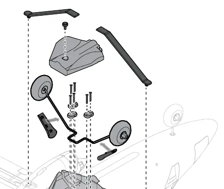
Landing Gear Installation: Loosen the screw on the bottom of the fuselage to remove the cover. Remove the six mounting screws from the clamps. Press the landing gear into the clamps until it snaps into position, then reinstall the gear in the fuselage and secure with the screws. Reinstall the cover and press the strut covers onto the wheel struts.
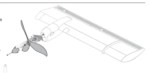
Propeller Installation: Determine the correct spinner and propeller for each side. Install the propeller adaptor on the shaft. Attach the left propeller (7056C) and right propeller (7056CR) to their respective adaptors, secure with the nut, and install the spinner with a 2mm x 10mm machine screw.
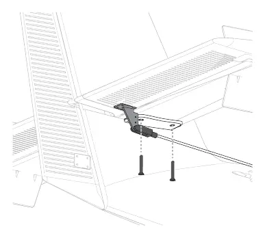
Horizontal Tail Installation: Slide the horizontal stabilizer into the hole in the vertical tail. Thread the four screws on the underside. Snap the elevator and rudder clevises into place, then snap the horizontal stabilizing fins into position.
Transmitter and Receiver Setup
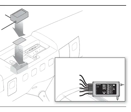
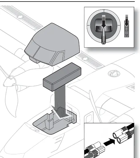
Receiver Installation (PNP): Mount the receiver parallel to the length of the fuselage using double-sided servo tape. Ensure control surfaces are attached to the correct ports.
Transmitter Setup: Start with a blank ACRO model. Set dual rates (High 100%, Low 70%), expo (High 20%, Low 15%), servo travel (100%), and throttle cut (-130%). Refer to the specific transmitter chart in the manual for detailed channel assignments and flap settings.
SAFE Select and AS3X Technology
SAFE Select: This feature provides flight envelope protection. It can be configured to be always OFF (AS3X mode), always ON, or switch-assignable. Binding the aircraft in a specific manner determines if SAFE Select is enabled or disabled.
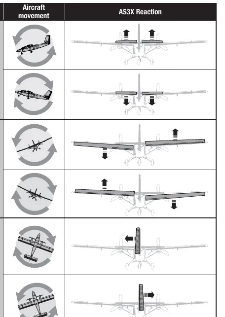
AS3X: This stabilization system is active whenever the battery is connected and the throttle has been raised above 25%. It helps the aircraft fly smoothly. If the aircraft oscillates, check for loose components or incorrect trim settings.
Maintenance and Repairs
Motor Service: Always disconnect the flight battery before service. Remove the spinner, propeller, and cowling screws. Disconnect motor wires from the ESC and remove the motor from the X-mount. Reassemble in reverse order, ensuring wire colors match.
Repairs: The EPO foam can be repaired using various adhesives like hot glue, CA, or epoxy. Do not use CA accelerant on the aircraft as it can damage the paint.
Troubleshooting
If the aircraft fails to bind, ensure the transmitter is not too close to the aircraft, the bind plug is installed correctly, and the battery is charged. If the aircraft experiences reduced flight time, check the battery charge, ensure the propeller is installed correctly, and ensure the battery is warm before use.
Practical help
Common problems
Aircraft will not bind to transmitter
Ensure transmitter is not too close to the aircraft, check that the bind plug is installed correctly, and verify battery charge.
Oscillation during flight
Check for damaged or imbalanced propellers, loose receiver, or loose control linkages. Ensure trim is neutral.
Reduced flight time or underpowered
Check if the flight battery is fully charged, ensure propellers are installed with numbers facing forward, and ensure the battery is warm.
Motor power pulses or loses power
The ESC may be triggering Low Voltage Cutoff (LVC). Recharge the battery or replace it if it is worn out.
Before use
- Charge flight battery fully.
- Set up transmitter with recommended dual rates and expo.
- Verify Center of Gravity (CG) is 45mm from leading edge of wing at the root.
- Perform control direction test.
- Perform AS3X control direction test.
- Ensure receiver is securely mounted.
Specs in practice
- CG (Center of Gravity)
- 45mm from the leading edge of the wing at the fuselage. Critical for stability.
Images and diagrams
- Landing gear installation: Shows screw locations and strut cover placement.
- Propeller installation: Indicates correct rotation and spinner attachment.
- Horizontal tail installation: Shows stabilizer insertion and clevis snapping.
- Receiver installation: Shows parallel mounting to fuselage.
Model compatibility
- Requires 3S 2200-3200mAh LiPo battery.
- Compatible with DSM2/DSMX transmitters.
- PNP version requires a 5+ channel receiver.

Manual page author
David Miller
Documentation analyst
Organizes user manual content into clear summaries, with attention to model details, product context, and everyday usability.