Home / Security
Uniview Villa Door Station User Manual
Quick guide for the Uniview Villa Door Station. Includes installation steps, wiring diagrams, default settings, and safety warnings for 2-button and 4-button models.
Table of contents
Manual images
Click an image to enlargeQuick Guide from the Manual
This document provides essential installation and setup instructions for the Uniview Villa Door Station, available in 2-button and 4-button configurations. It covers physical installation, wiring, and initial network configuration.
Packing List
Ensure your package contains the following items:
- Villa door station
- Wall mount bracket
- Screwdriver
- Screw components
- Paper nameplate
- Drill template
- Product documents
Device Overview
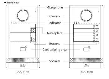
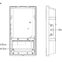
The door station features a camera, microphone, speaker, indicator lights, and buttons. The 2-button and 4-button models share the same installation methods. The rear panel contains the cable terminal interface, network interface, and a Micro SD card slot.
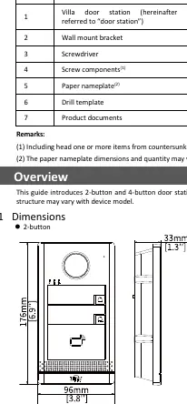
Device Installation
Preparation: Plan wiring based on networking conditions and prepare necessary tools like a Phillips screwdriver.
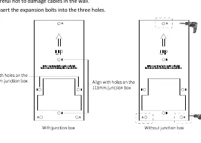
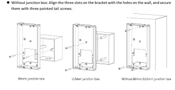
Wall Mount:
- Mount the junction box (86x86mm or 115x73mm) if applicable.
- Paste the drill template on the wall.
- Drill holes (6mm to 6.5mm diameter, 30mm depth) if not using a junction box.
- Secure the bracket to the wall or junction box using the provided screws.
- Install the Micro SD card (optional) by loosening the screw on the card slot cover.
- Install the sunshield (optional) by inserting it from the rear.
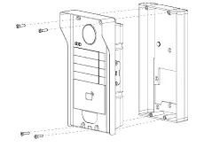
- Connect cables, fix the cable cover, and secure the door station to the bracket using Torx screws.
Recess Mount:
- Drill a recess and holes based on the bracket size.
- Secure the recess bracket into the wall.
- Complete the remaining steps (cabling, mounting) as described in the Wall Mount section.
Startup and Settings
Connect the device to a PoE power source via the network cable or use an external power adapter. The device will start automatically upon receiving power.
Default Settings:
- IP Address: 192.168.1.13
- Username: admin
- Password: 123456
Security Note: It is strongly recommended to change the default password immediately to a strong password containing at least nine characters, including uppercase/lowercase letters, digits, and special characters.
Safety and Maintenance
The device must be installed and maintained by a trained professional. Ensure proper ventilation, avoid stacking devices, and protect the unit from liquids. Do not hot-plug the Micro SD card. Always disconnect power before moving the device.
Manufacturer information
Uniview
Practical help
Common problems
Tamper-proof button sounding continuously
Ensure the rubber stopper is mounted correctly to the bracket protrusion to prevent loosening.
Device not powering on
Check the PoE connection or ensure the external power adapter is securely connected and providing stable voltage.
Micro SD card not recognized or damaged
Do not hot-plug the card. Power off the device before inserting or removing the card.
Before use
- Plan wiring based on actual networking conditions.
- Prepare Phillips screwdrivers and drill bits (6mm-6.5mm).
- Verify junction box size (86x86mm or 115x73mm) if using one.
- Ensure you have a strong password ready for initial setup.
- Check that the installation surface is flat and stable.
Specs in practice
- Default IP Address
- 192.168.1.13
- Default Login
- Username: admin, Password: 123456
- Indicator: Steady Red
- Calling
- Indicator: Steady White
- In a call
- Indicator: Steady Green
- Door is open
Images and diagrams
- Front View: Identifies the microphone, camera, indicator, nameplate, buttons, card swiping area, and speaker.
- Rear View: Shows the cable terminal interface, network interface, and Micro SD card slot location.
- Drill Template: Shows alignment holes for 86mm and 115mm junction boxes.
Model compatibility
- Supports both 2-button and 4-button door station models.
- Compatible with 86x86mm and 115x73mm junction boxes.
- Requires PoE or external power adapter.

Manual page author
Michael Turner
Technical manual editor
Reviews PDF manuals for structure, safety notes, and practical product details so readers can find the right information quickly.