Electronics / Intercom Systems
User Manual for Uniview Villa Door Station
Quick guide for the Uniview Villa Door Station. Includes installation steps, wiring diagrams, default login credentials, and setup instructions.
Table of contents
Manual images
Click an image to enlargeQuick Guide from the Manual
This document provides essential instructions for installing and configuring the Uniview Villa Door Station. It covers the physical installation, wiring requirements, and initial network setup. Always ensure the device is installed by a trained professional and that all local electrical safety regulations are followed.
Packing List
Before starting, ensure the package contains the following items. Contact your dealer if anything is missing:
- Villa door station
- Screw components
- Tail cable cover
- Tail cable
- T10 screwdriver
- Product documents
Device Appearance
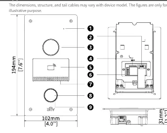
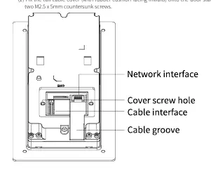
The door station features a microphone, lens, card reading area, and various interfaces. The rear panel includes the network interface, cable interface, and cable groove. The indicator light status is as follows:
- Steady white: Device is starting up.
- Off: Normal operation or power not connected.
Wiring and Cable Specifications
Proper wiring is critical for functionality. Connect the cables according to the following specifications:
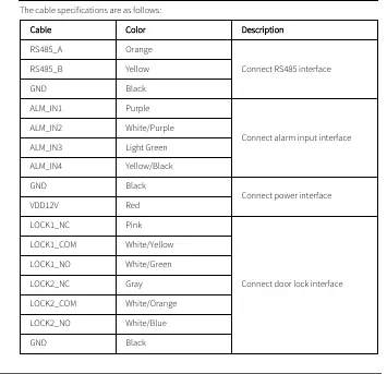
- RS485 interface: RS485_A (Orange), RS485_B (Yellow), GND (Black).
- Alarm input interface: ALM_IN1 (Purple), ALM_IN2 (White/Purple), ALM_IN3 (Light Green), ALM_IN4 (Yellow/Black), GND (Black).
- Power interface: VDD12V (Red), GND (Black).
- Door lock interface: LOCK1_NC (Pink), LOCK1_COM (White/Yellow), LOCK1_NO (White/Green), LOCK2_NC (Gray), LOCK2_COM (White/Orange), LOCK2_NO (White/Blue), GND (Black).
Installation
The device supports two main installation methods. Prepare tools such as an electric drill, Phillips screwdriver, marker, tape measure, ESD gloves, and a glue gun before beginning.
Wall Mount
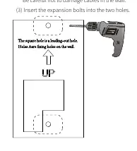
- Paste the drill template on the wall with the arrow pointing upward.
- Drill two 30mm-depth holes using a 6mm to 6.5mm drill bit.
- Insert expansion bolts.
- Fasten the bracket to the wall using M3.5 x 25mm screws.
- Connect all cables and fix the tail cable cover.
- Align the door station with the bracket and secure it with four M3 x 8mm screws.
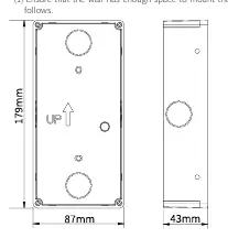
Recess Mount
- Fix the recess bracket into the wall. Ensure there is enough space.
- Paste the drill template and drill holes as marked.
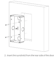
- Insert expansion bolts and fix the bracket to the wall.
- Insert the sunshield from the rear side of the door station.
- Connect all cables and secure the door station to the bracket.
Startup and Web Login
Once installed, connect the device to a PoE power supply or an external power adapter. To access the device settings:
- Default IP Address: 192.168.1.13
- Default Username: admin
- Default Password: 123456
For security, it is strongly recommended to change the default password immediately upon first login. Use a strong password containing at least nine characters, including uppercase and lowercase letters, digits, and special characters.
Safety and Maintenance
Ensure the device is installed in a proper environment, protected from liquids, and has adequate ventilation. Do not attempt to service the product yourself; contact a trained professional. Always disconnect power before moving the device. If using the device outdoors, ensure proper waterproof measures are taken.
Manufacturer information
Uniview
Practical help
Common problems
Indicator light is steady white
The device is currently starting up.
Indicator light is off
This indicates normal operation or that the device is not receiving power.
Security concerns regarding default credentials
Change the default username and password immediately after the first login.
Before use
- Ensure you have an electric drill, Phillips screwdriver, marker, tape measure, ESD gloves, and glue gun.
- Plan wiring based on actual networking conditions.
- Verify that the power supply provides a stable voltage meeting device requirements.
- Ensure the wall surface is flat and suitable for mounting.
- Check that the wall mount or recess bracket is purchased separately.
Specs in practice
- Default IP Address
- 192.168.1.13
- Default Login
- Username: admin, Password: 123456
- Drill Bit Size
- 6mm to 6.5mm for mounting holes.
Images and diagrams
- The appearance diagram identifies the microphone, lens, card reading area, and cable interfaces.
- The wiring table details the color-coded connections for RS485, alarm inputs, power, and door locks.
- Installation diagrams illustrate the drilling template positioning and bracket mounting steps.
Model compatibility
- Wall mount bracket and recess bracket/sunshield are not included and must be purchased separately.
- The device supports PoE power supply or external power adapter.

Manual page author
David Miller
Documentation analyst
Organizes user manual content into clear summaries, with attention to model details, product context, and everyday usability.