HVAC / Thermostats & Controls
White-Rodgers 1F78 Non-Programmable Thermostat User Manual
Comprehensive user guide for the White-Rodgers 1F78 non-programmable thermostat. Includes installation instructions, wiring diagrams, operating features, battery replacement, and troubleshooting steps.
Quick answers from the manual
Quick answer
- The White-Rodgers 1F78 is a non-programmable thermostat for 24V heating and cooling systems. It requires 2 AAA batteries and supports various wiring configurations, including heat pumps. p. 1, 2, 4
Key actions
- Reset the thermostat p. 5
- Replace batteries p. 2
First start
- Turn off power, label wires, mount base, connect wires, and install batteries. p. 1, 2
Problems and fixes
No Heat/Cool
Check fuse, power switch, and wiring connections.
p. 5Maintenance and reset
- Reset operation p. 5
Technical specifications
| Parameter | Value | Meaning | Pages |
|---|---|---|---|
| Electrical Rating | 0-30 VAC, 1.5A max | Maximum load per terminal 1.0A, total 1.5A. | p. 5 |
Where to find it in the PDF
- Installation and Wiring p. 1, 2, 3
- Operation p. 3, 4
- Specifications and Troubleshooting p. 5, 6
Table of contents
Manual images
Click an image to enlargeQuick Guide
The White-Rodgers 1F78 is a non-programmable thermostat designed for 24V heating and cooling systems. Before installation, ensure your system is compatible (see the compatibility chart in the PDF). The unit requires two AAA alkaline batteries to operate. Always turn off power at the main fuse box before beginning any installation or wiring work.
Installation and Wiring
Preparation: Before removing your old thermostat, label each wire with the terminal designation it was removed from. Do not let wires fall back into the wall.
Mounting: Remove the cover from the base. Use the base as a template to mark mounting holes on the wall. Drill holes, fasten the base loosely, level it, and tighten the screws. Push excess wire into the wall and plug the hole with fire-resistant material to prevent drafts.
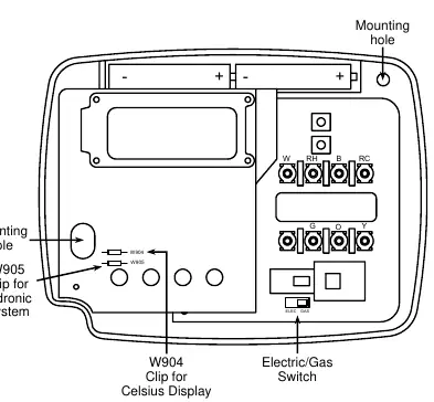
Wiring: Connect wires to the terminal screws on the base according to the specific wiring diagram for your system (e.g., heat only, cool only, heat/cool, or heat pump). Ensure the factory-installed jumper wire between RH and RC terminals remains in place for single-transformer systems.
Operating Features
Buttons and Switches: Use the Up/Down arrows to adjust temperature. The FAN switch toggles between ON and AUTO. The SYSTEM switch toggles between COOL, OFF, and HEAT.
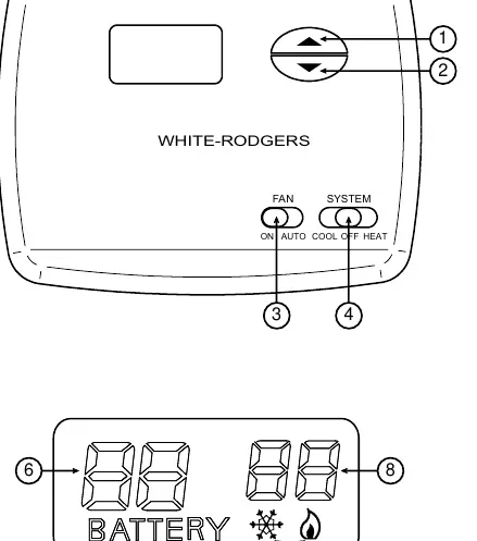
Display: The display shows the current temperature and the setpoint. A flashing snowflake icon indicates the compressor is in lockout mode (time delay).
Customization:
- Fahrenheit/Celsius: Clip the W904 jumper on the circuit board to switch to Celsius.
- Hydronic Systems: Clip the W905 jumper to adjust the heating cycle for hot water or steam systems.
- Temperature Adjustment: You can calibrate the displayed temperature by +/- 3 degrees by pressing the Up and Down arrows simultaneously for two seconds while the system is in OFF mode.
- Backlight: Enable the backlight by pressing the Up and Down arrows simultaneously for two seconds while in HEAT mode, then toggle to ON.
Troubleshooting
If the display is blank or the thermostat behaves erratically, perform a reset: press the Up and Down arrows simultaneously while moving the SYSTEM switch from OFF to HEAT. This restores factory defaults. If the system does not heat or cool, check for blown fuses, ensure the furnace power switch is ON, and verify that all wires are securely connected to the terminals.
Specifications
The thermostat operates on 0 to 30 VAC 50/60 Hz or D.C. The setpoint temperature range is 45°F to 90°F (7°C to 32°C). It is designed for 24V systems and is not compatible with line voltage (110/240V) or multistage systems.
Practical help
Common problems
No Heat/No Cool/No Fan
Check for a blown fuse or tripped circuit breaker. Ensure the furnace power switch is ON and the blower compartment door is properly closed.
Blank Display
Replace the 2 AAA batteries. If the display remains blank, perform a reset by pressing the Up and Down arrows simultaneously while moving the SYSTEM switch from OFF to HEAT.
Heat/Cool/Fan runs constantly
Check for shorted wiring at the terminals. Ensure the FAN switch is set to AUTO, not ON.
Before use
- Label all wires before disconnecting the old thermostat
- Turn off electricity at the main fuse box
- Verify system compatibility (24V systems only)
- Install 2 fresh AAA alkaline batteries
- Ensure the system switch is set to OFF before installation
Specs in practice
- Electrical Rating
- 0 to 30 VAC 50/60 Hz or D.C.; 1.5 Amps maximum total load.
- Setpoint Range
- 45°F to 90°F (7°C to 32°C).
- Operating Humidity
- 0 to 90% RH (non-condensing).
Images and diagrams
- Figures 2-7 provide specific wiring schematics for various HVAC configurations (Heat only, Cool only, Heat/Cool, Heat Pump).
- Figure 1 illustrates the base layout, including the location of the W904/W905 jumpers and the Electric/Gas switch.
Model compatibility
- Not compatible with line voltage (110/240V) systems.
- Not compatible with multistage systems.
- Requires 24V systems.

Manual page author
Emily Carter
User documentation editor
Prepares concise manual descriptions and highlights the most useful setup, operation, and maintenance information for readers.