HVAC / Thermostats & Controls
Installation and Operation Instructions for White-Rodgers 1F80-51 Programmable Thermostat
Comprehensive installation and operation guide for the White-Rodgers 1F80-51 programmable thermostat. Includes wiring diagrams, battery installation, programming schedules, and troubleshooting tips.
Quick answers from the manual
Quick answer
- The White-Rodgers 1F80-51 is a programmable digital thermostat for single-stage heating and cooling systems. It supports 5-day/2-day programming, battery operation, and features a built-in short-term compressor protection delay. p. 1, 4
Key actions
- Install batteries p. 2
- Program schedule p. 6
First start
- Remove battery tag, mount base, connect wires according to diagram, set Electric/Gas switch, and program schedule. p. 2, 6
Problems and fixes
Display shows BATTERY
Replace with 3 fresh 'AA' Energizer alkaline batteries.
p. 2Maintenance and reset
- Replace batteries when 'BATTERY' is displayed. p. 2
Technical specifications
| Parameter | Value | Meaning | Pages |
|---|---|---|---|
| Electrical Rating | 8 to 30 VAC 50/60 Hz or D.C. | Operating voltage range. | p. 1 |
| Temperature Range | 45°F to 90°F | Setpoint range. | p. 1 |
Where to find it in the PDF
- Specifications and Features p. 1
- Installation p. 2
- Wiring Diagrams p. 3
- Operation and Programming p. 4, 5, 6
Table of contents
Manual images
Click an image to enlargeQuick Guide from the Manual
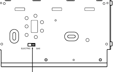
The White-Rodgers 1F80-51 is a programmable digital thermostat designed for single-stage heating and cooling systems. Before installation, ensure the power is disconnected at the main fuse box. This unit is for low-voltage systems only; do not use it with line voltage. The thermostat requires 3 AA alkaline batteries to operate. Ensure the electric heat switch on the back of the base is set correctly (ELECTRIC for heat pumps/central electric, GAS for others) before mounting.
Installation
Removing Old Thermostat: Shut off electricity. Remove the front cover of the old unit, label wires, and disconnect them one by one. Do not let wires fall back into the wall.
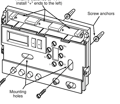
Mounting: Remove the packing material and gently pull the cover off the base. Connect wires to the terminal screws according to the provided wiring diagrams. Use the base as a template to mark and drill mounting holes. Fasten the base to the wall, ensuring it is level. Push excess wire into the wall and plug the hole with fire-resistant material to prevent drafts.
Operation
Buttons and Switches: The thermostat features buttons for setting time, viewing/running programs, holding temperature, and switches for fan (ON/AUTO) and system (COOL/OFF/HEAT). The display shows the day of the week, current time, temperature, and system status.
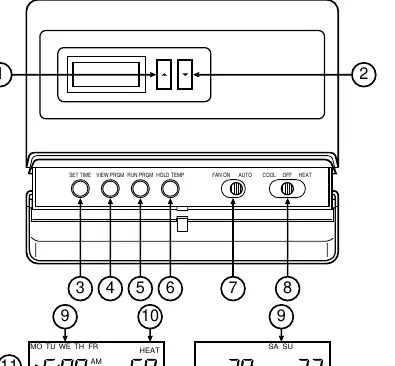
Programming: You can program heating and cooling schedules for 5-day (weekday) and 2-day (weekend) periods. Use the SET TIME button to set the current time and day. Use the VIEW PRGM button to navigate through the four daily program periods and adjust temperatures using the arrow buttons.
Operating Features
- Temperature Override: Temporarily override the current program until the next period begins.
- Hold Temperature: Maintain a specific temperature indefinitely until manually cancelled.
- °F/°C Convertibility: Press and hold SET TIME and HOLD TEMP buttons simultaneously to switch units.
- 12/24-Hour Clock: Toggle between formats by pressing and holding SET TIME and RUN PRGM.
- Low Battery Indicator: If the display is blank except for 'BATTERY', replace the 3 AA batteries.
Troubleshooting
If the system does not operate properly during testing, contact a qualified serviceperson. If the cooling system does not start, ensure the outdoor temperature is above 50°F, as the thermostat will not operate the cooling system below this temperature to prevent compressor damage.
Practical help
Common problems
Display is blank except for the word 'BATTERY'
The batteries are low. Replace with 3 fresh 'AA' Energizer alkaline batteries.
Cooling system will not start
Ensure the outdoor temperature is above 50°F. The thermostat locks out the compressor in cold weather to prevent damage.
System does not operate during testing
Verify all wiring connections and power supply. If the issue persists, contact a qualified serviceperson.
Before use
- Disconnect electrical power at the main fuse box before installation.
- Verify your system is low voltage (do not use on line voltage).
- Remove the battery tag from the back of the thermostat to engage power.
- Set the Electric/Gas switch on the back of the base to the correct position for your system.
- Ensure the thermostat is level for aesthetic purposes.
Specs in practice
- Electrical Rating
- 8 to 30 VAC 50/60 Hz or D.C.; 1.5 Amps maximum total load.
- Setpoint Temperature Range
- 45°F to 90°F (7°C to 32°C).
- Operating Humidity
- 0 to 90% RH (non-condensing).
Images and diagrams
- Figure 1: Shows the location of the Electric/Gas switch on the back of the thermostat base.
- Figure 2: Illustrates battery installation (positive ends to the left) and mounting hole locations.
- Figures 3-10: Provide specific wiring diagrams for various system configurations (heating only, heat/cool, heat pump, etc.).
Model compatibility
- Compatible with standard heat/cool, electric heat, gas/oil, hydronic, and single-stage heat pump systems.
- Not compatible with multi-stage systems, systems exceeding 30 VAC/1.5 amps, or 3-wire zoned hydronic heating systems.

Manual page author
David Miller
Documentation analyst
Organizes user manual content into clear summaries, with attention to model details, product context, and everyday usability.