HVAC / Thermostats & Controls
Installation Instructions for White-Rodgers 1F51N-619 Evaporative Cooler Thermostat
Quick guide for the White-Rodgers 1F51N-619 Low Voltage Evaporative Cooler Thermostat. Includes installation steps, wiring precautions, operation modes, and technical specifications.
Quick answers from the manual
Quick answer
- The 1F51N-619 is a low voltage evaporative cooler thermostat. It requires installation by connecting wires to the subbase terminals, mounting the subbase to the wall, and attaching the thermostat base. It operates on 24VAC and is designed for use with the 8A18Z-2 control. p. 1, 2
Key actions
- Mounting the subbase p. 2
- Setting temperature p. 2
First start
- Remove shipping packing p. 2
Technical specifications
| Parameter | Value | Meaning | Pages |
|---|---|---|---|
| Switch Rating | 24VAC (30VAC max) | Maximum voltage capacity | p. 1 |
| Cooling Amps | 0 to 1.5 Amps | Current capacity for cooling | p. 1 |
Where to find it in the PDF
- Installation and Specifications p. 1
- Installation and Wiring p. 2
Table of contents
Manual images
Click an image to enlargeQuick guide from the manual
This document provides installation and operation instructions for the White-Rodgers 1F51N-619 Low Voltage Evaporative Cooler Thermostat. Important: Always disconnect electrical power at the main fuse or circuit breaker box before beginning installation to prevent electrical shock or equipment damage. This thermostat is designed to operate with the White-Rodgers 8A18Z-2 Evaporative Cooler Control.
Installation
Follow these steps to install the thermostat:
- Route wires: Pull wires from the cooling equipment through the hole in the wall, leaving approximately 6 inches of cable protruding.
- Connect wires: Pull wires through the opening near the center of the subbase and connect them beneath the terminal screws as indicated in the wiring diagram.
- Seal opening: Push excess wiring back into the wall and plug the hole with fire-resistant material (e.g., fiberglass insulation) to prevent drafts from affecting the thermostat.
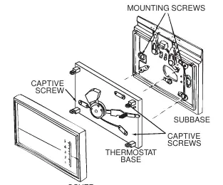
- Mount subbase: Fasten the subbase loosely to the wall using two mounting screws. Use a level against the bottom of the subbase to adjust until level, then tighten the screws.
- Attach thermostat: Attach the thermostat base to the subbase, ensuring all captive screws are tightened snugly, as these serve as electrical connections.
- Finish: Snap the cover onto the thermostat base and set the temperature lever to the desired setting (1 to 5 scale).
Operation
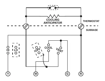
The thermostat features a subbase switch for system control and a fan switch for speed selection.
- System Switch: Allows selection of VENT, COOL, or OFF positions.
- Fan Switch: Allows selection of LOW or HIGH fan speed.
- Temperature Scale: Numbers 1 to 5, where lower numbers represent cooler temperatures and higher numbers represent warmer temperatures.
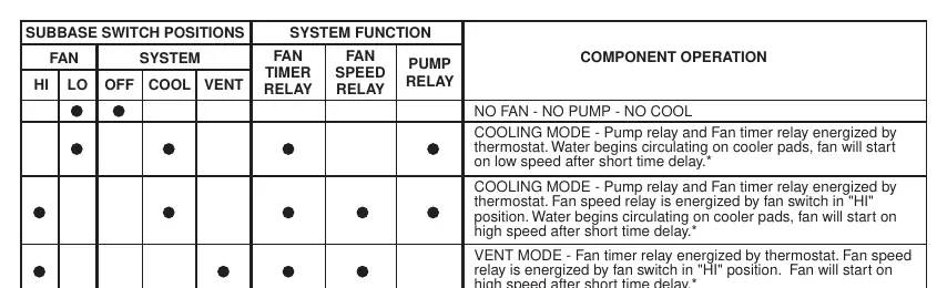
The system function depends on the combination of switch positions. For example, in COOLING MODE, both the pump relay and fan timer relay are energized by the thermostat, and the fan starts on low or high speed depending on the fan switch setting.
Safety and Precautions
- Electrical Safety: Do not use on circuits exceeding 30 volts. Higher voltage will damage the control and cause shock or fire hazards.
- Wiring: Do not short out terminals on the gas valve or primary control to test. Incorrect wiring will burn out the heat anticipator.
- Mercury Warning: This product does not contain mercury, but it may replace a unit that does. If replacing a mercury-containing unit, do not discard it in household trash; follow proper disposal procedures as outlined at www.white-rodgers.com.
Official resources from the manual
Practical help
Common problems
Thermostat not functioning or equipment damage
Ensure wiring is not shorted to adjacent terminals or the rear of the thermostat. Verify that the voltage does not exceed 30 volts.
Heat anticipator burnout
Do not short out terminals on the gas valve or primary control to test the system.
Drafts affecting thermostat operation
Ensure the hole in the wall behind the thermostat is plugged with fire-resistant material like fiberglass insulation.
Before use
- Disconnect electrical power at the main fuse or circuit breaker box.
- Verify that the system wiring is low voltage (do not use on circuits exceeding 30V).
- Ensure compatibility with the White-Rodgers 8A18Z-2 Evaporative Cooler Control.
- Have a level tool ready for mounting the subbase.
- Remove shipping protective packing from the switch before attaching the cover.
Specs in practice
- Switch Rating
- 24VAC (30VAC max); Cooling 0 to 1.5 Amps.
- Temperature Scale
- 1 to 5 scale; 1 is cooler, 5 is warmer.
- Differential
- 1°F.
Images and diagrams
- The wiring diagram illustrates connections for the Fan (HI/LO) and System (OFF/COOL/VENT) switches.
- The installation diagram shows the subbase, captive screws, and mounting screw locations.
Model compatibility
- Designed specifically to operate with the White-Rodgers 8A18Z-2 Evaporative Cooler Control.

Manual page author
Emily Carter
User documentation editor
Prepares concise manual descriptions and highlights the most useful setup, operation, and maintenance information for readers.