HVAC / Thermostats & Controls
White-Rodgers 1F56N-444 Thermostat User Manual
A comprehensive guide for the White-Rodgers 1F56N-444 thermostat, covering installation, wiring diagrams, heat anticipator adjustment, operation, and troubleshooting.
Quick answers from the manual
Quick answer
- The 1F56N-444 is a snap-action thermostat for standard heating/cooling systems. Installation involves removing the old unit, mounting the subbase, connecting wires according to the terminal cross-reference, and setting the heat anticipator. p. 1, 8
Key actions
- Adjusting Heat Anticipator p. 2, 7
- Mounting Subbase p. 1, 8
First start
- Turn on power after installation and use the system switch to select Heat or Cool. p. 2, 7
Problems and fixes
No Heat/No Cool/No Fan
Check fuse/breaker, ensure power switch is ON, check furnace door panel.
p. 3, 6Technical specifications
| Parameter | Value | Meaning | Pages |
|---|---|---|---|
| Switch Rating | 24 VAC (30 VAC max) | Electrical rating for the thermostat. | p. 2, 7 |
| Heat Anticipator | 0.15 to 1.2 Amps | Adjustable range for heating cycles. | p. 2, 7 |
Where to find it in the PDF
- Installation Instructions p. 1, 8
- Wiring Diagrams p. 2, 7
- Troubleshooting p. 3, 6
Table of contents
Manual images
Click an image to enlargeQuick guide from the manual
This document provides installation and operation instructions for the White-Rodgers 1F56N-444 thermostat. Before starting, ensure you have the necessary tools: power drill, flat blade screwdriver, wire cutter/stripper, and a level. Important: Always disconnect electrical power at the main fuse or circuit breaker before beginning installation to prevent shock or equipment damage.
Removing the old thermostat
A standard heat/cool thermostat consists of three basic parts:
- Cover: May be snap-on or hinge type.
- Base: Removed by loosening all captive screws.
- Switching subbase: Removed by unscrewing the mounting screws holding it to the wall or adaptor plate.
Note the anticipator setting on the old thermostat for future reference.
Mounting and wiring
Follow these steps to mount the new thermostat:
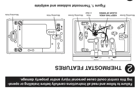
- Mounting: Use the screws provided to mount the subbase or wallplate to the wall. Ensure the area is clear of wires.
- Wiring: Attach wires to the appropriate terminals. Use the terminal cross-reference chart provided in the manual to determine correct connections.
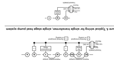
- Jumper settings: If your system has more than two wires, check the factory-installed jumper between RH and RC. For electric heat or single-stage heat pump systems that require the thermostat to energize the fan, move the yellow jumper wire from the Y terminal to the A terminal.
- Finishing: Gently push excess wire back into the wall opening and plug the hole with fire-resistant material (e.g., fiberglass insulation) to prevent drafts. Mount the thermostat base to the subbase using the three captive screws.
Setting the heat anticipator
The heat anticipator is adjustable from 0.15 to 1.2 Amps. To adjust:
- Rotate the contact arm to match the current rating stamped on your main heating control.
- Move the pointer counterclockwise to lengthen heating cycles or clockwise to shorten heating cycles.
- Adjustments should not be greater than 1/2 marking at a time.
Operation
Once power is restored, use the system switch to select heating or cooling. Use the fan switch to control fan operation:
- AUTO: Fan runs with the heating or cooling system.
- ON: Fan runs continuously, regardless of the system switch position.
Troubleshooting
If you encounter issues, check the following:
- No Heat/No Cool/No Fan: Check for a blown fuse or tripped circuit breaker, ensure the furnace power switch is ON, and verify the furnace blower compartment door is properly installed.
- Furnace cycles too fast/slow: Adjust the heat anticipator setting.
- Thermostat thermometer disagrees with room temp: Use a standard slotted screwdriver to turn the thermometer pointer screw inside the front cover to calibrate.
Practical help
Common problems
No Heat/No Cool/No Fan
Check fuse/breaker, ensure furnace power switch is ON, and verify furnace blower door is closed.
Furnace cycles too fast or too slow
Adjust the heat anticipator setting (Step 5).
Thermostat thermometer inaccurate
Adjust the thermometer pointer screw located inside the front cover.
Before use
- Disconnect electrical power at the main fuse or circuit breaker.
- Label each wire with the terminal designation before removing the old thermostat.
- Ensure tools (drill, screwdriver, wire stripper, level) are ready.
- Verify system compatibility (e.g., 24V systems).
Specs in practice
- Switch Rating
- 24 VAC (30 VAC max).
- Heat Anticipator
- Adjustable from 0.15 to 1.2 Amps.
- Temperature Range
- 50°F to 90°F (10°C to 32°C).
Images and diagrams
- Figure 1: Shows the subbase and wallplate mounting.
- Figures 2-7: Provide wiring diagrams for various system configurations (single/two transformer, heat pump, etc.).
- Figure 5: Illustrates how to adjust the heat anticipator.
Model compatibility
- Compatible with standard heating/cooling systems (4 or 5 wires).
- Compatible with gas, oil, or electric furnaces.
- Not for use on circuits exceeding specified voltage.
- Not compatible with line voltage (120/240V) baseboard electric heating.

Manual page author
Michael Turner
Technical manual editor
Reviews PDF manuals for structure, safety notes, and practical product details so readers can find the right information quickly.