Automotive / Motorcycle Accessories
Installation Guide for Yoshimura Fender Eliminator Kit 075BG194700
Quick installation guide for the Yoshimura Fender Eliminator Kit 075BG194700 for CFMOTO 675 SS. Includes removal, assembly, and wiring instructions.
Table of contents
Manual images
Click an image to enlargeImportant Information
This Yoshimura Fender Eliminator Kit (075BG194700) is designed for the CFMOTO 675 SS. Please note that this product is not DOT approved and is not intended for use on public highways. Always check local laws and regulations for compliance prior to installation and use.
Removal of Stock Fender
- Remove the passenger seat.
- Locate and disconnect the license plate light and turn signal connectors.
- While securely supporting the stock fender assembly, remove the three bolts securing it.
- Carefully remove the stock fender assembly, ensuring you do not damage the license plate light and turn signal connectors.
Installation
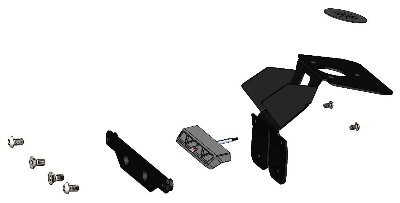
- Install the Yoshimura license plate light (075BG-LH-C1) onto the fender eliminator bracket (19470-FEBKT) using the M4X6BHS button head screws.
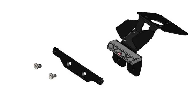
- Install the license plate bracket (FE-LP-BKT) onto the fender eliminator bracket (19470-FEBKT) using the M6X12FS-SS flat head screws.
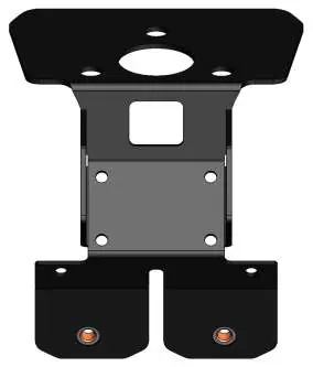
- Install the stock tail light onto the fender eliminator bracket using the four stock screws. Route the tail light connector through the square slot.
- Install the wire debris cover (H-2158T-1) into the fender eliminator bracket hole.
- Mount the fender eliminator bracket (19470-FEBKT) to the under-tail using the stock fender mounting bolts. Torque to factory specifications.
Wiring Connections
Route the license plate light wires through the wire debris cover, into the tail section, and connect to the wiring harness as follows:
- Black (light) to Green (harness)
- Red (light) to Brown (harness)
Route the stock tail light wire connector through the wire debris cover, into the tail section, and re-connect to the wiring harness.
Final Checks
- Re-install the passenger seat.
- Check for proper function of the license plate light, turn signals, and brake light.
- Ensure all brackets and components are secure prior to riding.
Practical help
Common problems
Product legality
This product is not DOT approved and not intended for use on public highways. Check local laws before use.
Wiring confusion
Connect the Black wire from the light to the Green wire on the harness, and the Red wire from the light to the Brown wire on the harness.
Before use
- Check local laws and regulations for compliance.
- Verify all brackets and components are secure.
- Test license plate light function.
- Test turn signal function.
- Test brake light function.
Images and diagrams
- The assembly diagram illustrates the correct order of screws, washers, and nuts for the license plate bracket.
- The wiring section provides specific color-coding for the light harness connections.
Model compatibility
- Designed specifically for the CFMOTO 675 SS.

Manual page author
Michael Turner
Technical manual editor
Reviews PDF manuals for structure, safety notes, and practical product details so readers can find the right information quickly.