Automotive / Motorcycle Accessories
Installation Guide for Yoshimura Micro Turn Signal Kit for Honda Grom
Step-by-step installation guide for the Yoshimura Micro Turn Signal Kit on Honda Grom. Includes removal of stock signals, wiring instructions, and assembly details.
Table of contents
Manual images
Click an image to enlargeQuick guide from the manual
This kit is designed for the Honda Grom. Please note that the white running light wire and red brake light wire on the micro signals are not used; bundle them back and tuck them away. A red front light is prohibited in most states; check local laws and regulations prior to installation.
Parts included
- Right Front Turn Signal Plate (074BG121220-R)
- Left Front Turn Signal Plate (074BG121220-L)
- Turn Signal Backing Plate (074BG121210-B) x2
- 6mm x 12mm Button Head Cap Screw (M6X12BHS) x2
- M6 x 1.0 Nylon Lock Nut (6MMLN) x2
- Micro LED Turn Signal Kit (072BGMICRTSR)
Removal of stock turn signals
- Remove the four bolts securing the headlight assembly to the frame and carefully pull out the headlight assembly.
- Locate and disconnect the left and right turn signal connectors.
- Remove the meter cover by unscrewing the two bolts on the underside and gently pulling down.
- Locate and unscrew the cap nut holding the turn signal in place.
- Disassemble and remove the left and right turn signals from the turn signal holder.
- Cut the stock turn signal wires 4 inches from the connector.
Installation
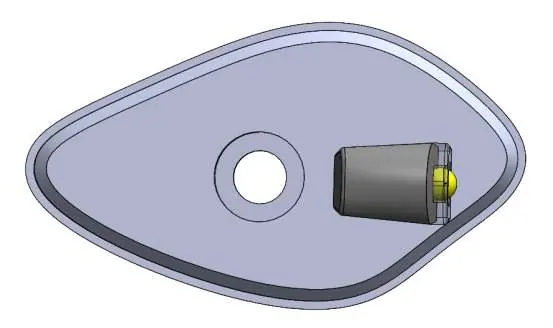

- Place the micro turn signal in the front hole and the plastic hex nut in the inside pocket of the adapter plate. Note: If the turn signal is not facing forward, remove and rotate the plastic nut in the adapter plate pocket and re-install. Repeat until the signal is facing forward.
- Install the micro turn signal and front turn signal plate onto the outside of the turn signal bracket.
- Install the turn signal backing plate on the inside of the turn signal holder and secure using the M6X12BHS screw and 6MMLN lock nut.
- Repeat steps for the opposite side.
- Re-install the meter cover by lining up the cover with the back of the meter, ensuring it rests on the front side of the adapter plate for the best fit. Re-install the back cover screws.
Wiring and electrical connection
Use the solder shrink connectors supplied in the kit to connect the turn signal wires to the micro light wires as follows:
- Right (Blue Connector): Green (Harness) to Black, Blue (Harness) to Blue.
- Left (Orange Connector): Green (Harness) to Black, Orange (Harness) to Blue.
Connection procedure:
- Strip the stock turn signal wire ends 1/4 inch to 1/2 inch and insert into the provided solder shrink connectors.
- Center the spliced wire ends in the middle.
- Using a heat gun or lighter, apply heat evenly on the outer edges of the connector to shrink and hold wires in place.
- Heat the center of the connector evenly until the solder begins to liquify.
- Allow to cool completely and tug both ends of the wires to verify that the connection is secured.
Final checks
Re-install the headlight assembly using the four stock bolts. Check for proper function of the headlight and turn signals, and ensure all components are secure prior to riding.
Practical help
Common problems
Turn signal not facing forward after installation
Remove the signal, rotate the plastic nut in the adapter plate pocket, and re-install.
Wiring connection feels loose
Allow the solder shrink connector to cool completely, then tug both ends of the wires to verify the connection is secured.
Before use
- Check local laws regarding red front lights.
- Ensure you have a heat gun or lighter for the solder shrink connectors.
- Verify all components are secure before riding.
- Check headlight and turn signal function after re-installation.
Images and diagrams
- The exploded view shows the assembly order of the turn signal, adapter plate, backing plate, screw, and nut.
Model compatibility
- Designed specifically for Honda Grom.

Manual page author
David Miller
Documentation analyst
Organizes user manual content into clear summaries, with attention to model details, product context, and everyday usability.