Electronics / AV Converters
Installation Instructions for Channel Vision CVT 1STEREO Multi-Room Video Modulator
Comprehensive installation and configuration guide for the Channel Vision CVT 1STEREO and 1UB/2UB/3UB/UHF series video modulators. Includes wiring diagrams, channel mapping, system design considerations, and troubleshooting steps.
Quick answers from the manual
Quick answer
- The Channel Vision CVT Modulator allows you to map audio/video sources to unused TV channels for multi-room distribution. Installation involves connecting sources to the modulator, setting the channel via DIP switches, and integrating the signal into your existing TV network. p. 2
Key actions
- Setting Channels p. 2, 3
- Adjusting Signal p. 2, 3
First start
- Connect video sources to inputs, connect RF output to the combiner, connect combiner to TV network, and plug in the unit. p. 2
Problems and fixes
Snowy Picture
Verify the modulator and TV are set to the same channel band (UHF vs. Cable). Ensure the modulated channel is not blocked by the TV's auto-programming.
p. 4
Black Picture
Verify video source connections. Disconnect the modulator to isolate if the issue is with the source or the modulator.
p. 4Technical specifications
| Parameter | Value | Meaning | Pages |
|---|---|---|---|
| RF Output | 35dBmV | Maximum output level | p. 7 |
| Operating Temperature | 0°C to 50°C | Operating range | p. 7 |
Where to find it in the PDF
- Installation Instructions p. 2, 3
- Troubleshooting p. 4, 5
- Wiring Diagrams p. 6
- Specifications p. 7
Table of contents
Quick Guide from the Manual
The Channel Vision CVT Modulator allows you to map audio/video sources to unused TV channels for multi-room distribution. The system merges additional inputs into your existing TV signal, making sources like security cameras, VCRs, or stereo systems available on every TV connected to your coax network.
Basic Installation
Follow these steps to set up your modulator:
- Power Off: Always ensure the unit is powered off before changing DIP switch settings.
- Channel Selection: Use the DIP switches on the back of the unit to set the desired frequency band (UHF or Cable).
- Connections: Connect your video sources to the inputs on the back of the CVT Modulator. Connect the RF output to one input of the supplied combiner, and your existing cable/antenna signal to the other.
- Network Integration: Connect the output of the combiner to your TV network and plug the modulator into a wall outlet.
- Channel Tuning: Turn on your TV. Press the SELECT button on the modulator to cycle through inputs (A, B, or C). Hold SELECT for two seconds until the light blinks to enter channel-change mode, then use the UP/DOWN buttons to select the desired channel.
System Design Considerations
For optimal performance in sophisticated home networks, consider the following:
- Signal Strength: Aim for 10dBmV at each television. Signals below 10dBmV may result in snowy pictures, while signals above 10dBmV may overdrive older TVs.
- Amplification: Use broadband amplifiers (5MHz to 1GHz) to compensate for signal loss over long cable runs.
- Filtering: Use low-pass filters to clean up frequencies and prevent interference from active channels.
- Termination: Cap all unused coax cable ports with 75-ohm terminators to prevent signal leakage.
Troubleshooting
If you encounter issues, try these common solutions:
- Snowy Picture: Verify the modulator and TV are set to the same channel band (UHF vs. Cable). Ensure the modulated channel is not blocked by the TV's auto-programming.
- Black Picture: Verify video source connections. Disconnect the modulator to isolate if the issue is with the source or the modulator.
- Interference/Wavy Lines: Check for beat frequencies or unbalanced signal. Adjust the attenuator on the back of the unit or use a tilt compensator.
- Overheating: Ensure the unit is installed in a well-ventilated area.
Specifications
The CVT series modulators feature a PLL synthesized oscillator, NTSC video support, and adjustable gain. Operating temperatures range from 0°C to 50°C. Power consumption is 8 Watts.
Practical help
Common problems
Snowy Picture
Verify the modulator and TV are set to the same channel band (UHF vs. Cable). Ensure the modulated channel is not blocked by the TV's auto-programming.
Black Picture
Verify video source connections. Disconnect the modulator to isolate if the issue is with the source or the modulator.
Interference/Wavy Lines
Check for beat frequencies or unbalanced signal. Adjust the attenuator on the back of the unit or use a tilt compensator.
Picture Tearing
Check that the impedance switch is set to 75 ohms.
Before use
- Power off the unit before changing DIP switch settings.
- Ensure all splitters and amplifiers are broadband (5MHz to 1GHz).
- Verify signal strength is approximately 10dBmV at each TV.
- Use high-quality shielded coax (RG6 Quad or RG11).
- Use a low-pass filter on every installation to clean up frequencies.
Specs in practice
- Frequency Ranges
- UHF 471.25-855.25MHz; Cable 433.25-859.25MHz.
- Operating Temperature
- 0°C to 50°C.
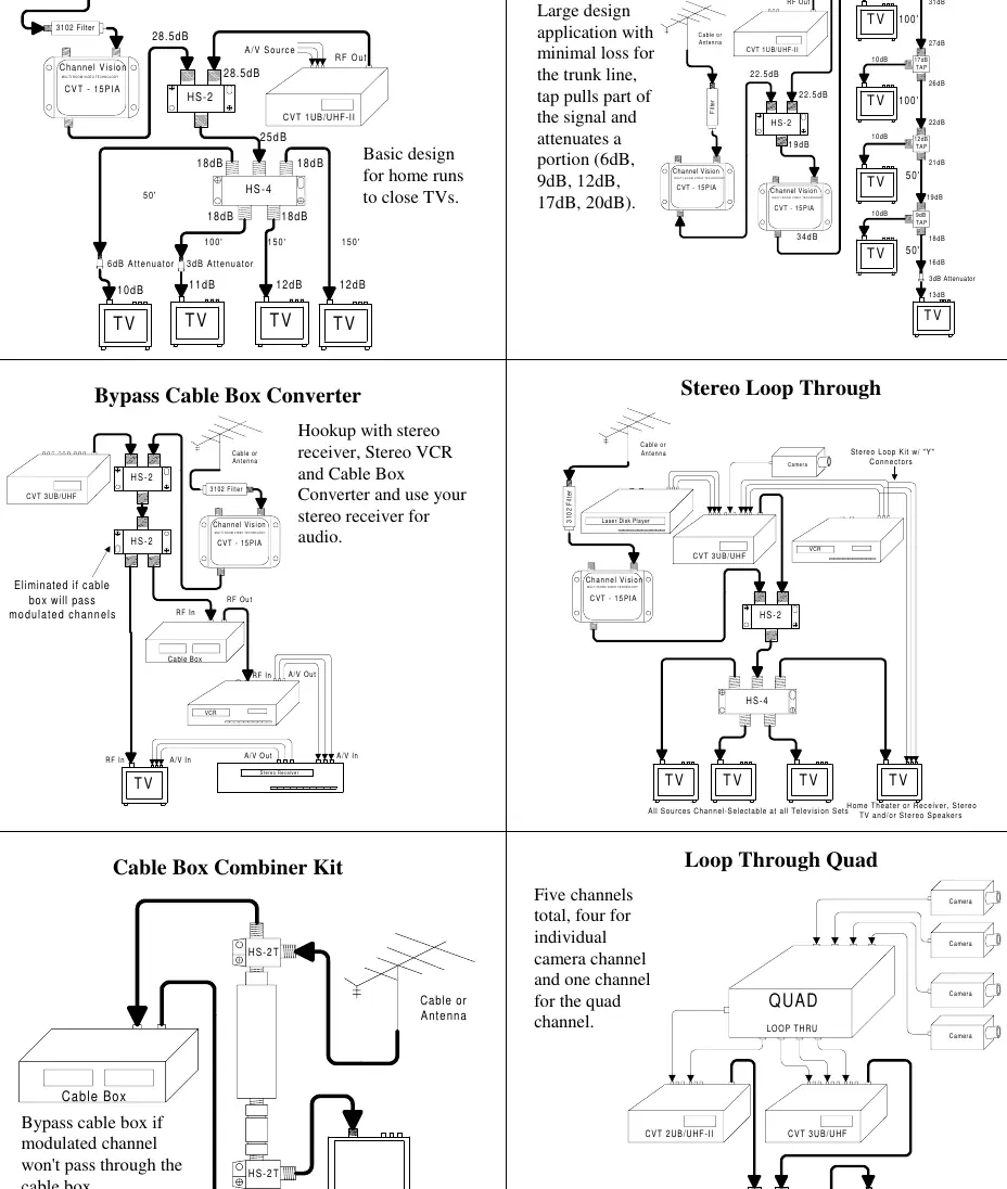
Images and diagrams
- Splitter/Home Run Design: Basic setup for distributing signals to multiple TVs.
- Bypass Cable Box: Routing modulated signals around a cable box.
- Stereo Loop Through: Integrating stereo audio with video sources.
Model compatibility
- Compatible with NTSC video systems.
- Requires broadband splitters and amplifiers (5MHz to 1GHz).
- Not for use with cable boxes that do not pass modulated signals without a bypass kit.

Manual page author
Michael Turner
Technical manual editor
Reviews PDF manuals for structure, safety notes, and practical product details so readers can find the right information quickly.